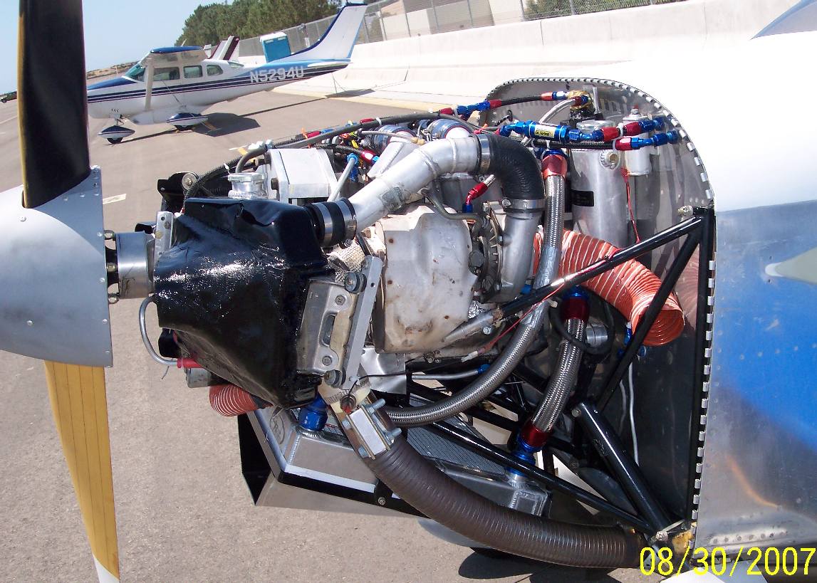
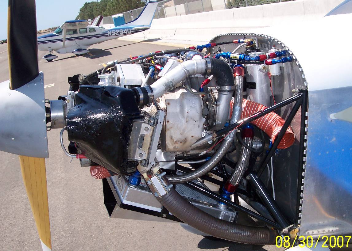
Well, I am pleased to report that my turbo, stock housing with TO4
wheel and 60-1 compressor with a fixed open waste gate has lasted
over 230 hrs without a single problem. The solution to good enough?
Make it better. I just finished my annual during which I upgraded
my turbo to a similar TO4 big shaft wheel, but now it has a TO4E 50-
trim compressor and the wastegate flapper and actuator are back in
place. Why the change? Either I am a glutton for punishment or I
am starting to pin down this turbo issue. For those of you not
familiar with my turbo history, here is a quick recap:
First turbo - the stock second generation with waste gate flapper
installed, ridden hard and put away wet... it was run at full
throttle at high altitudes, often at peak EGT. It lasted 70 hrs
before the turbine wheel fell apart and broke off. The thought at
the time was that the stock turbo was just too small for this heavy
duty abuse and was overspeeding at altitude.
Second turbo - small shaft TO4 wheel with 60-1 compressor and
removed waste gate flapper. It was also run mostly at peak EGT but
the power produced was somewhat lower because of the bypassed
exhaust. It lasted about 140 hrs until it suffered the same fate as
the first turbo while I was in a long full power decent (read extra
high RPM and EGT's). My thinking at this point is that the high
EGT's are primarily the problem.
Third Turbo - The one I just removed after 230 hrs. Same
configuration as the second but I kept the EGT's under 1600, mostly
as lean as I could while keeping the engine running not too rough.
It was also run at pretty low pressure ratios. It could only make
about 38" MAP on take off and about 40" at full bore down lot. At
16k altitude it was down to about 22". My curiosity now is weather
I can perhaps increase the boost and continue to have the turbo last,
as long as I keep the EGT's under 1600. I know, glutton for punishment...
Other issues..
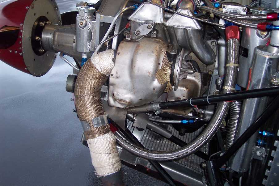
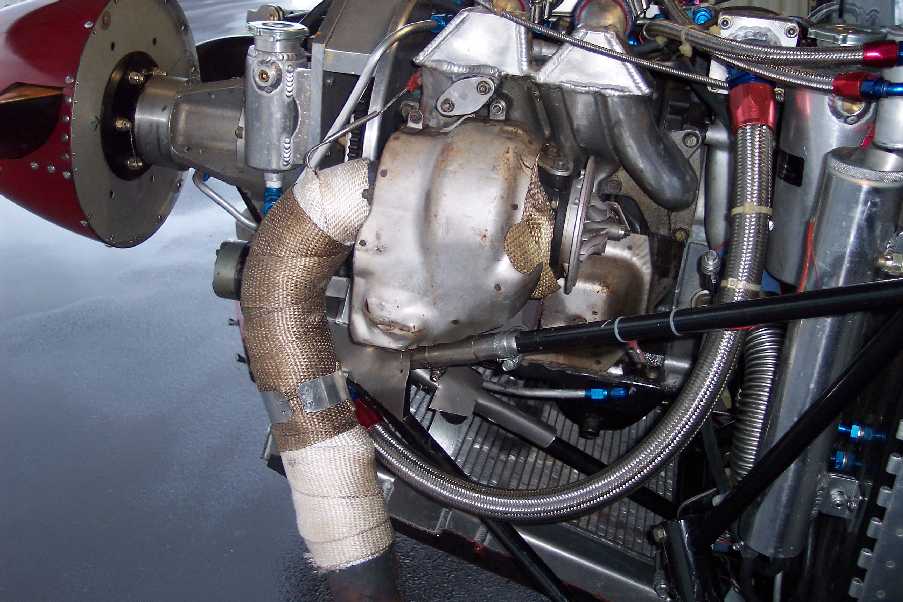
Lean of Peak operation. During the turbo change I discovered that
my stock cast iron exhaust manifold had developed a number of
serious cracks and some advanced erosion. Much of the
erosion/oxidation was near the mating surface with the turbo and it
had started a small leak. My concern is that all those hours of LOP
operation allows too much oxygen into the exhaust to promote to
oxidation and accelerates the problem. The question is, should I
start running rich of peak to prevent rusting away the exhaust
system components? ROP operations also allow me to keep even lower
EGT's (for the turbo) and smoother engine running (for the wife).
Turbos and exhaust components that I get from cars usually have the
appearance of being run rich, rather than the dry orange color of
the inside of my components. The only obvious downside is the
obvious much increased fuel usage. I think that for the next couple
hundred hours I have going to have to bite the bullet and fly ROP
(while at higher power settings). Thoughts?
S.A.G. is really baffling. Spark plugs only seem to be lasting 20-
30 hrs before SAG starts kicking in. Noted by a distinct and marked
loss of power as I cross through about 1500' AGL after take off.
The problem is usually intermittent and mildish at first becoming
more consistent and remarkable as the hours accumulate on the spark
plugs. The problem is always solved by changing out the spark
plugs. I am switching to colder platinum plugs in order to try to
get them to last longer. Perhaps running ROP will help them last
long too?
Time for a new Prop? On a test flight yesterday, the engine was
running great. No SAG. At 7000' and 33"MAP I was at 6500 RPM,
about 1/3 throttle and doing 175 KTAS [201 MPH]. It is a 64
length x 77 pitch 3-blade Cato, but that is more like an
effective pitch of closer to 71". I seem to remember being able
to get closer to 185 KTAS [213 MPH] at 6500 RPM in the past on
the same prop but I did have a little taken off because of the
low output of the previous turbo. After some more experience I
may discover that it is time for another new prop. Might soon
contact Paul Lipps, I liked his article in the last issue of
Contact! mag. If that is my worst problem, I am going to be
pretty happy.
Doing some formation flying with the guys next week that may make
its way into a movie...
Keep building!
--
David Leonard
Turbo Rotary RV-6 N4VY
http://N4VY.RotaryRoster.net <
http://n4vy.rotaryroster.net/ <
http://n4vy.rotaryroster.net/
http://RotaryRoster.net <
http://rotaryroster.net/ <
http://rotaryroster.net/
I really appreciate Dave's persistence on exploring
turbo charged rotaries in aircraft use.
The turbo life issue is not only the EGT it is the turbo RPM as well.
If the RPM is high enough the blades will disintegrate regardless
of the turbine inlet temp. The load on the blades is M times V
squared divided by R. V is the the tangential velocity of the blade
CG. M is the mass of the blade. R is the radius of the blade CG. All
rotating device suffer from this problem. As the temp goes up the
strength of the blade material is reduced. At 1600 F strength of
exhaust valve steel is down to 5000 psi which is next to nothing.
See the attached chart. Epoxy resin is 3000 psi :)
Here is a chart from Caterpillar on the situation. The turbine
MUST be kept within the limit lines of both temperature AND rpm.
I have repeatably tried to get Dave to install a Garret turbine
RPM kit. In fact I will buy it and send it to him. No luck
so far. If you send me the compressor Dave I will install
the RPM sensor for you and send it back as well. Perhaps Zack can
convince him :) We need to know the turbine RPM!!!!!
Somebody needs to try a Capacitor Discharge ignition system
to further investigate the spark plug "sag" problem.
Inconel is probably the only answer to high temp corrosion
of ferrous materials. I have seen many cracked cast iron
turbo exhaust manifolds.
Paul Lamar
Hi Dave,
Auto OEM "wisdom" dictates running rich while boosted to prevent
detonation.
Also autos are regularly being accelerated off lights etc, which will give
the
black soot.
How would ceramic coating the turbine housing work to keep heat out of the
metal? You would have to compensate for the thickness of the ceramic at
the
mating surfaces or have them masked off so you do not coat those areas.
Dale Davies
Dave,
What is your new turbo make, number and trim? Same as the Cozy
Girls but with a built in waste gate? I have a similar cast
iron manifold as yours and you are welcome to have it. That
will get you in air fast. A better long term solution would be
if I donate a custom fabricated exhaust manifold to your
cause. I can with your dimensional assistance design and
manufacture a stainless 316L with altered pipe ells, It would
have a tangential junction connecting both runners so that an
external wastegate could divert the exhaust flow BEFORE it hit
the turbine. It will be more robust and lighter than the Mazda
cast iron manifold you are now using. Paul can attest to the
quality of the welds at the shop near me. Most of their works
is fabricating exotic alloys and they can guarantee fitting by
using my 13B assembled engine.
In return I as well as others need flight data. If you can fly
to at least 18k, and cruise rpms near or over 6K engine rpm
then the data you collect will be invaluable for not only my
project but scores of turbo rotary want- to-be's. Paul will
lend you a turbo tach and I believe a few of us could cobble up
a ten channel flight recorder so you don't have to take notes.
What do you say?
Doug in Japan.
Now that is an offer you should not refuse Dave.
Doug's shop is second to none.
3/16th inch thick 316 SS plate is ten times better than cast iron.
Here is a simple design that will divert the exhaust
gas before it reaches the turbine. The is the ultimate waste
gate. Zero to 100%. This 3D could be dimensionally interchangeably with
the stock cast iron 1990 manifold Dave is using now. Same
dimensions.
Paul Lamar
HI Doug,
Wow, that is quite an offer and I am inclined to take you up on it if you
really want the data that badly, but I don't really need anything for the
time being (and IMHO, turbo tach data will not be particularly useful to
you
either). But first to answer your questions.
I am using the stock series 5 housing and That is the ONLY thing that will
fit. Really, I have tried everything. My clearances are very tight and
changing one little thing cause a ripple effect that could keep me
grounded
for a year or more. Simply nothing else will fit. Not even Pauls
manifold
and wastegate above - the exhaust pipe from it would pass through my
radiator...
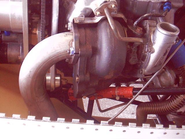
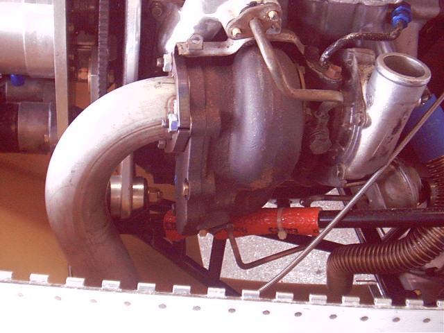
So given that I am stuck with the stock series 5 manifold and housing, it
is
ported larger to fit a big shaft turbine with and aggressive trim (not
sure
which one) Compressor and housing can be changed out to almost any of the
TO4 compressors. I had some nice pictures showing my mods to the turbo,
but
just accidentally deleted them trying to move them to my computer.
Anyway, the manifold cracks are not a big deal. I had a couple of spare
ones sitting around for just this occasion, and it could still probably be
used for many more hours. Though someday I may change it out for a SS
manifold of the exact same dimensions. In fact, if you think your shop
could make me an essential copy of the stock series 5 turbo exhaust
manifold
(89-91) then I would be glad to install Pauls turbo tach and get you all
the
data you want. But I think it needs to be smooth flow, not a box type.
Box
is likely to cause unacceptable back pressure. Internal pipes would
probably need to be supported by some sort of box, as the turbo has no
other
support. No need for a wastegate, as there is no place for me to send the
exhaust. I am stuck using the stock (but ported) internal wastegate.
That is a pretty big and difficult project (would cost me a pretty penny
for
such a custom manifold) and I don't think it is worth your while. Let me
explain. We have turbo maps that give us a very good approximation of the
turbo speed for given conditions. Paul argues that there are too many
unknown factors in the mass flow so the maps are not that accurate. Ok
fine. But suppose the map predicts that the turbo is turning 90k RPM and
the tach shows it turning 100k. (the difference is unlikely to be
particularly large) What now? We don't really know where we should be
drawing the line for continuous operation because it is a gray area trade
off between performance and durability. Maybe you could fine tune your
compressor selection a little, but I am already running the biggest
(slowest
turning) compressor that matches the mass flow that I can find. There are
bigger compressors, but they require much higher mass flows.
And if we do collect data, it really tells us more about the unknowns of
my
system (like volumectric efficiency and intercooler pressure drop. etc)
than
helping you design your system. And those unknowns are going to change
between particular installations.
None the less, if you are still interested, I would love to have a nice
custom SS manifold and as soon as it is done will fly up and "let" Paul
help
me install the turbo tach and come along to collect data if he wants. (or
I
can do it myself, it is not hard to collect data). One thing, since I
cant
really run WOT with this turbo anywhere close to the ground (if at all)
(it
would over boost the engine), we really need to also measure the pressure
upstream of the throttle body which will require the borrowing and
installing of a manifold pressure sensor as well. (not a huge issue)
--
David Leonard
Turbo Rotary RV-6 N4VY
http://N4VY.RotaryRoster.net <
http://n4vy.rotaryroster.net/ <
http://n4vy.rotaryroster.net/
http://RotaryRoster.net <
http://rotaryroster.net/ <
http://rotaryroster.net/
The turbo tach is NOT about turbo performance.
The turbo tach is NOT about boost level.
IT IS ABOUT STRESS ON THE BLADES.
Stress = M X V squared over R.
R is one M is one. 90K RPM squared is 8,100K.
100K RPM squared is 10,000K RPM .
10,000 divided by 8,100 is 24% more stress on the blades!!!!!!!
Small increases in RPM makes a huge difference in stress!!!!!
The stock 91 manifold has the turbo located in a asymmetric
location and just about 4 inches from the face of the rotor
housings. The diameter of the exhaust ports is 2 inches ID.
Assume for the moment we used the tightest tubing bend
we can find. That would be a 304 stainless railing casting
From RB Wagner. The center line radius is 2 inches.
As you can see from this to-scale-3D it is just not practical.
What ever you build it will turn into a box like
chamber and that is the reason Mazda did it that
way. There is just no room for a streamlined turbo
manifold that fits the stock turbo position.
Perhaps it could be done with a SS casting but the pattern
alone would cost thousands and the length of the runners
would be drastically different.
Perhaps it could be NC machined in two pieces of billet SS
and welded together but that would also be rather expensive
and the runner length would still differ.
Paul Lamar
Dave,
I was also thinking along the design lines you mentioned. This
being smooth flowing pipes joining to the central inlet plate.
I believe the local guys can custom formed some pipe sections or
at least order them out. Not easy to make but can be done. To
accomplish this I was going to suggest the manifold be
symmetrical. This would allow the joining of another pipe that
interfaces with the two runners and is situated below them so
that an off-the-shelf new type flapper bypass valve could be
installed. This outlet would be flanged and a cap plate attached
until such time as you try turbocharger version number 5 and
want a waste gate before the turbine:)
The downside for you is this design would shift your turbo
charger position aft an inch or so crowding your inlet hose?
If this is acceptable I will start drawing. Sounds like you
have the same engine I have.
I agree with you that the turbo and compressor performance
mapping is best done experimentally. I find compressor maps
interesting but they only describe potential, not actual
performance. Reading about your and John Slade's performance
issues, it seems like the built-in wastegate on your model is
too small. Even all the way open it is not able to open far
enough to bypass all the flow. Hence you may be boosting more
than you desire down low. Where did you acquire TC number 4?
Any idea on the turbine AR.trim, and maker.
John Slade has told me his P trim TE04-E- 50 unit is holding up
OK. You mentioned 60-1. His unit compressor being 50 would
indicate it can achieve a higher C/R. Can it flow enough air
though? Compressor are a like water pumps. The design
efficiency is biased toward high pressure or high flow. We get
one at the efficiency expense of the other. If the gas flow is
available brute force can get us acceptable levels of both.
Correct me if I am wrong but I believe with your turbo-charger,
you can achieve at least 33-34" MAP at 18K ASL.. That is a few
inches over normalization of course and the compressor is
operating a wee bit over 2:1. pressure ratio.
The turbo tach data does have some advantages as we will have to
create a test program to map out the performance of the
compressor at different altitudes and boost pressure. Knowning
your temps and rpms. we can make an operations chart before
hand and thus creep up on performance limits carefully.
Also<85.Do you have room for a 3.5 inch diameter mass flow
meter say before the compress inlet? After the intercooler is
best location but I imagine there is no room. I got one it on
E-bay used. They are inexpensive but I can lend it to you for a
few months if you wish.
Drop me a line directly if there are other issues you need to
discuss. SKYPE also works for me if you want to
teleconference.
Doug in Japan
fir@gol.com
Hi Doug,
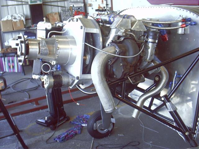
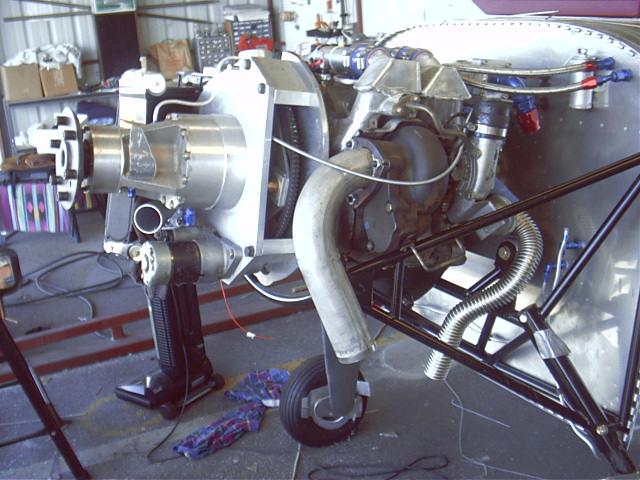
Unfortunately, unless I want to start moving everything around, like
building a new engine mount, the turbo cannot be moved even a small amount.
Moving the turbo up, in, fore or aft will make the compressor housing hit
the intake manifold. Because it is a larger TO4 compressor housing it has
to be ground down in areas as it is. I will get some pictures one of these
days and show you what I mean. Moving the turbo out or down will make it
hit the engine mount. as it is, it is less than 1mm from the SS heat shield
and the clearance makes getting the turbo installed over the studs quite a
miracle each time I manage it.
You are right about the wastegate, it would be nice to have one with more
authority that could keep the heat away from the turbo all together. There
may be some space underneath the front rotor outlet, but not the rear rotor
because the radiator and coolant hose run there. Again, will have to get
some pictures.
There is some space down, aft, and outside the engine mount where I could
probably re-mount the turbo. Or MAYBE just a little aft and out. Course
that would require re-doing the exhaust pipes, intake pipes, oil line, and
coolant lines. I would have to create support brackets and an oil sump with
a separate oil pump for oil return. I would have to make a new air inlet in
the cowl and cover the old one.. that would require fiberglass work and then
trying to match the paint and re-painting. You get the picture. Seems like
a lot of work for an airplane that currently outperforms most other RV's
(until the next turbo dies).
Show me some pictures of the air-flow meter. I may be able to find a place
to fit it in for some testing. That data would probably be as useful as
turbine speed and I wont have to drill any holes in my compressor housing.
You are right about high flow vs high pressure compressors. And indeed my
best guess calculations show what we want is somewhere between the 60-1 and
TO4E -50. However, if I get a bigger prop I can slow down the engine a
little and reduce the air flow which would move me right onto the cent
efficiency island of the TO4E.
Paul should note that for any given combination of altitude and power
setting that I am likely to be at, the TO4E -50 will be turning 5K RPM
slower than the 60-1, and it is the lowest turning compressor that I can
find (for any given settings).
I have my turbo made up at BNR supercars:
http://bnrsupercars.com/
I get the stage 4 upgrade for the series 5 (second generation) turbo. I do
not know the make or trim of the turbine.
I have only take the TO4E for one flight so for. The stock turbo could make
about 30" MAP at 18k. Will get some good data on some long trips I have
planned in the next few weeks.