Paul--I an email related to discussion of designing simple
inductive ignition systems using trigger wheels with segments to
set dwell and I.R. pickups to provide a simple system with no
computer. That is what we used, in various configurations, on
all our engines from 1988-1998. We worked with Mallory to
improve the heat resistance of their early I.R. units and these
units became very reliable and remain readily available. These
are shown on attached photos.
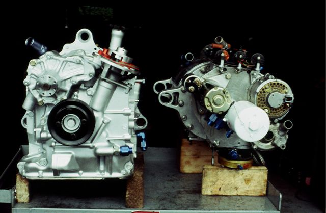
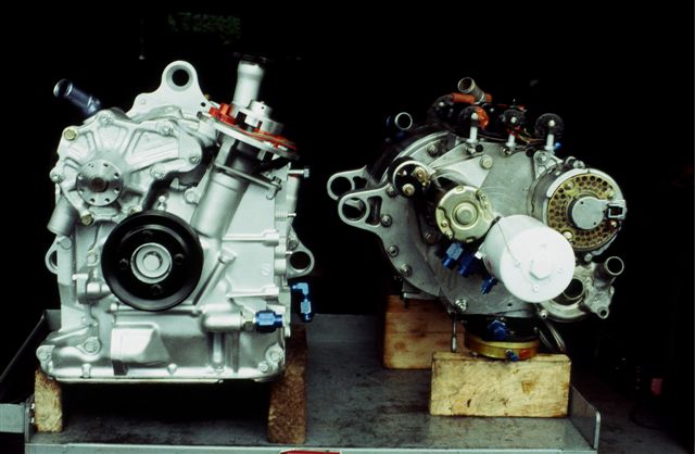
The first photo shows the rear view of the Mazda conversion
PS200 prototype engine sitting next to the last SuperLight
engine (as installed in aircraft). I put the two engines side by
side for comparison photos when we took the Superlight out of
the RV-4 and installed it in the RV-3 for the Sun'n Fun
competition.
On this photo comparing the two engines, visable is the trigger
wheel mounted in the Mazda distributor/CAS housing on the
conversion engine but the eccentric-mount trigger and pickups on
the SL are covered.
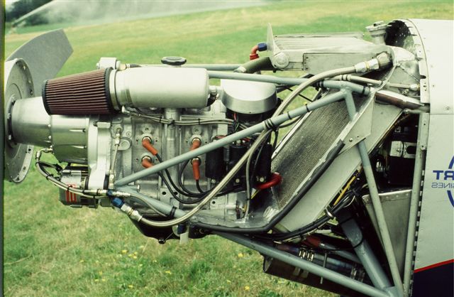
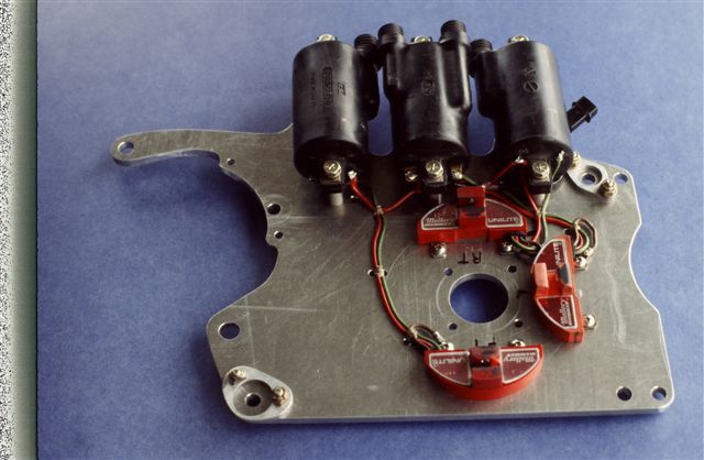
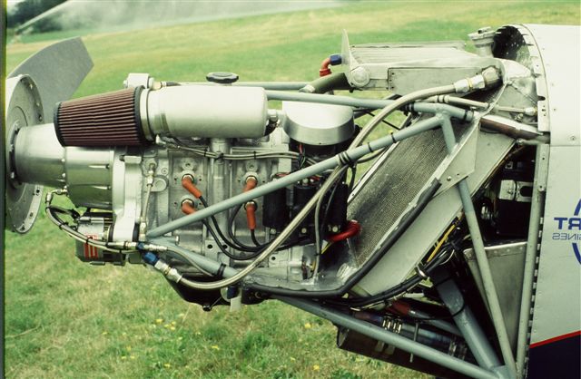
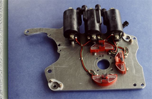
On all SuperLight engines we used an eccentric-mounted trigger
wheel. The first system we built for the original SL engine is
shown sans-trigger wheel in the third photo enclosed. This
photo shows the Mallory pickups screwed to the attach plate and
coils also. This unit was bolted to the back of the engine and
was on the engine when I flew the first prototype SL in the RV-4
to Oshkosh in 1991. We refined this system for the last gen SL
engine, machining the the trigger wheel segments, rear
counterweight and ring gear into a single piece with a taper
machined to bolt it to the Mazda eccentric shaft.
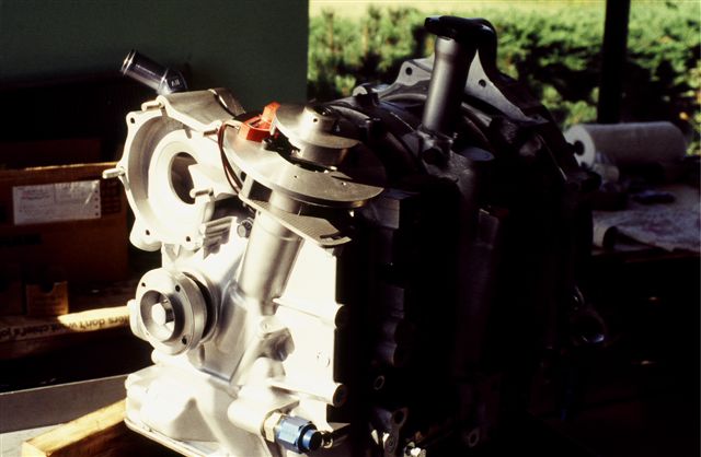
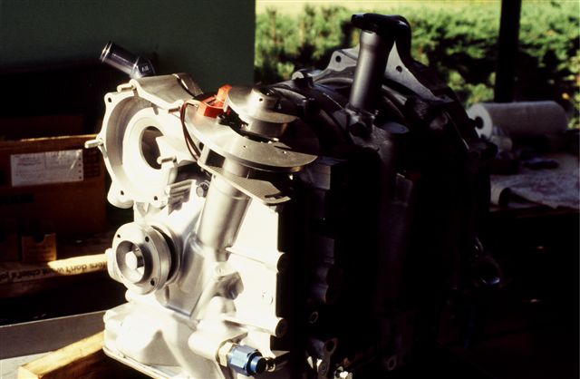
On the Mazda conversion prototype shown (this is the engine we
flew in the RV-4 and RV-3), we milled a small trigger wheel from
aluminum billet that attached to the unmodified Mazda
distributor/CAS unit. The plate holding the Mallory pickups
was turned on the lathe and attached to the stock Mazda
distrib/CAS with screws. The ignition housing cap shown in
photos was turned out of an old large aluminum piston and
secured to the pickup plate with three small set screws. We
designed this system to fit in Mazda distributors and crank
angle sensors with the intent of using the most possible
stock-based Mazda core components. This system was flown in the
RV-4 and RV-3 from 1995 until October 1997 and it performed
flawlessly. When you were here last year, a replica of this
ignition unit was installed on the two-rotor in the new RV-3.
In preflight, the leading/trailing circuits on all systems
regardless of configuration were each checked on run-up with
leading/trailing switches on the panel. All systems used three
Honda motorcycle coils. Although theoretically the
crank-trigger system provides more accurate timing due to
absence of gear lash, etc. we found no measurable nor subjective
difference in operation of the distributor/CAS-based
configuration vs. eccentric trigger systems.
Steve Beckham
Thanks Steve. You guys were way ahead of the curve.
Paul Lamar
--
The Rotary Engine NewsLetter. Powered by Linux.
ACRE NL web site.
http://www.rotaryeng.net
Youtube key word PaulLamar2
Copyright 1998-2010 All world wide rights reserved.