Hi
I am trying to find out more information on the link front
end shown on the roadable page of your website.
I live in Brisbane Australia and am looking at building
a land speed record bike with my son over the next couple of years.
Any information would be greatly appreciated.
Thanks
jon
http://www.rotaryeng.net/roadable.html
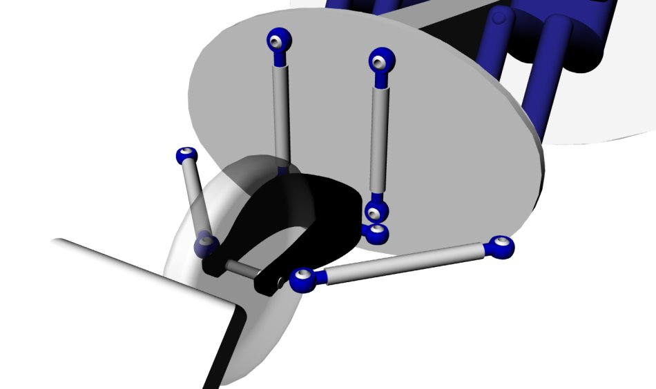
That is a virtual caster pivot ahead of the center of the
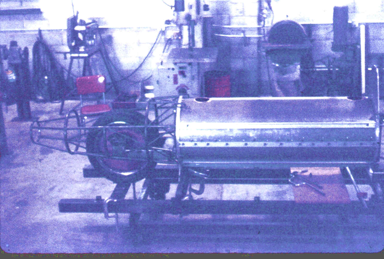
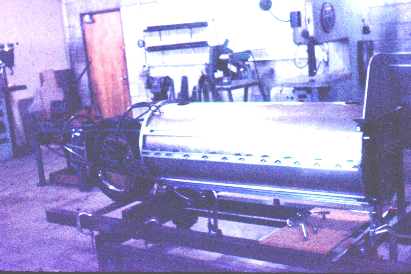
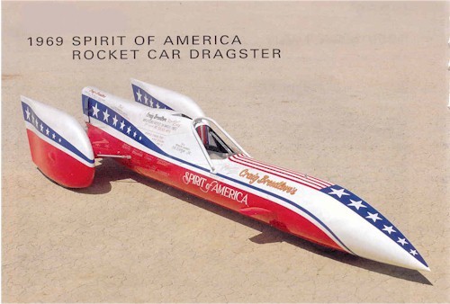
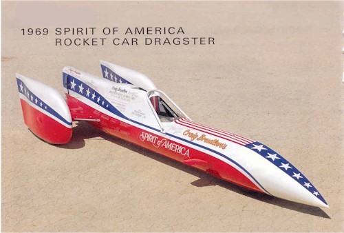
tire patch. I designed that for one of Craig Breedloves
rocket powered land speed record cars. Tested to over
400 MPH :)
Old message on the subject.
Quote:
Paul,
I am very pleased to finally find the designer of this part.
Everyone who looked at the link found it ingenious. Craig and his 2000-2006
crew chief, David Schmidt, were very, very proud of the design. The first
day I saw the car in 2006, David did two things that I had an issue with:
First, he claimed credit for the link even though I knew he was not on the
original build crew. Second, he tried to dazzle me; saying that I could
never figure out how it worked. I'm a flight test ME/AE, and have built
vehicles in 4 different motorsports. David was out of his league with me
and everyone I brought in. So I started questioning Craig about the
original build and the people involved. I never got a straight answer on
anything.
The fact is, I recognized immediately that the lower links pointed at the
steering center. The problem was, Craig had set it up with zero trail. I
had never heard of any steering setup working with zero trail and this made
me question the steering stability. The upper links were harder for me to
understand, since they were parallel. I understood right away that this
created camber with the steering angle, much like a fork front suspension.
Since the whole assembly compressed the shocks when steered, there was a
significant centering force with the car in the air, but not with weight on
the wheels.
Something bothered me about this, and it took a month for me to figure it
out. If we have a single, round profile tire the camber change with
steering angle would be correct. If, on the other hand, we have multiple
front wheels then the positive steering axle camber would lead to negative
roll.
The lack of trail I knew was neutral in stability, the adverse roll was
unstable. I did some research and found that wobble/weave stability was
best at ~5% trail vs. total wheelbase. Less would lead to steering wobble,
more would couple into the chassis and lead to weave. The 1996 accident was
a yaw-roll-yaw-roll-yaw-roll oscillation that looked surprisingly like a
motorcycle weave.
Looking at the car, we designed new lower-aft link brackets that would put
the steering center 18" forward of the axle. This respected 5% of the
wheelbase of 360". I also wanted to flatten out the roll, or even make it
proverse instead of adverse. So we extended the lower vertical link mounts
so that we had a vertical center near the ground plane.
We needed to test this before we got any further. We took the car out in
the parking lot (~100 yds of flat pavement) and pushed it to less than 5
mph.
1. With the 1996-97 setup, the car spontaneously diverged to one side
or the other and full-lock steering would not correct it. The tire tracks
clearly showed only the tire opposite the steering command was on the
ground.
2. With the roll taken out, the car would go straight until we turned
the wheel. Then it would turn in that direction and not come back even with
a full-lock reversal.
3. Once we put the trail in, it steered straight, turned when we
turned the wheel, and straightened itself out hands off.
4. We then repeated the test as fast as we could push. It worked the
same up to 7-8 mph.
Every amateur aerodynamicist (and many professionals who should know better)
believed that the roll was cause by "SHOCK WAVES!!!" under the car. This
never stood up to even the simplest analysis. First, at M.89 it wasn't
going fast enough for shocks of any significant strength to bounce off of
the porous-plastic surface of the playa. Shock waves do reflect, but they
lose energy when doing so and typically don't come back up one half of the
significant length of the object that created them until we get above M1.2
to 1.3 at the point of the reflection. Second, the leading edges of the
struts were swept at 75 degrees which means they would not create a shock
until M3.8! Yes, there were probably local shocks from the intersections
at the leading edge vs. the fuselage and wheel fairing. These would be
pretty weak at M.89 on the high fineness ratios of the strut, fuselage, and
wheel fairing.
Craig was convinced that gyroscopic forces from turning the wheels rolled
the car. I did some quick math and this just didn't add up. The car did
roll in the direction of the engine torque, but it rolled back almost to
level against that torque. The oscillation was also clearly discrete in
roll vs. yaw: first yaw without roll, then roll without yaw, reverse,
repeat.
One last thing about the focusing link: on Sonic Arrow the vertical links
angled slightly aft at the top. This loads them in compression and puts
high shear stress on the pivots. I thought it would be better, if
mechanically less convenient, to move the upper vertical mounts forward and
unload the vertical links. When I visited the Chicago Museum of Industry, I
persuaded the management to let me crawl up in the front wheel well of the
original Spirit of America. The vertical links were installed the way I
would have expected. I think Sonic Arrow was done the way it was for the
mechanical convenience of mounting the links to a common plane, in this
case, the front of the fuel tank structure. SOA had the steering forward of
the driver.
I'd like to hear about everything you did on all of Craig's cars. We've had
to do a lot of forensic engineering and need to know about all of the theory
that went into each area of the design.
Eric Ahlstrom
President, Star Aerospace LLC
Guilty as charged. How is Craig? I have not heard from him in years.
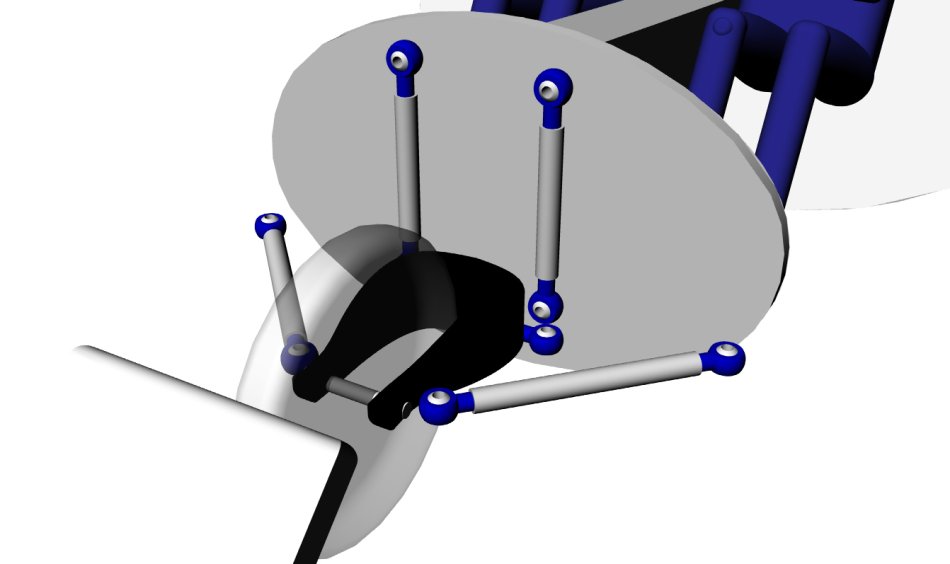
The links form a virtual pivot ahead of the tire contact patch so it forms a
caster effect.
Here is an example of such a system on my flying motor cycle design.
The two vertical links control the camber of the wheel and the lateral link
mounted at the back of the wheel controls the steer angle. Craig said it
worked very well up to 400 MPH.
http://www.rotaryeng.net/roadable.html
I only worked on the American Motors V8 powered version around
the early
70's. Margie Smith, a mechanical engineer from a mining school in Colorado
did all the drawings. That car was intended to achieve the
wheel driven land speed record. Little is known about this car as it never
set any records. On November 12th 1965 the Goldenrod held the wheel driven land speed
record at an average speed of 409.277 mph (658.526 kph).
I did a manual analysis using a Friden mechanical calculator of the speed
verses time/distance and told Craig I did not think we had enough room at
Bonneville to achieve 400 MPH with the intended power and tire traction available.
I used inverted wings between the fuselage and rear wheel pants to apply
down force to improve the traction. Craig said not to worry and showed
me some Jato bottles. He intended to fire at the start. I said the best
place to fire them was around 375 MPH when the real estate was being used
up much more rapidly.
The following is hearsay. Craig told his ex wife about the Jato
bottles and she told her boy friend who happened to know Joe Petrilli(S?)
of the USAC (I think) sanctioning body. Joe called Craig and said three
words. "No Jato bottles." AMC cut the funds and I was laid off. As I understand
it The V8 was removed and a spare lunar landing rocket motor was installed. Craig
did a demo run at a drag strip and achieved 400 MPH in the quarter mile.
The car was banned as too dangerous on drag strips. Craig later told me
he took it to Bonneville and could not get it much above 400 MPH due to
not enough fuel storage. It was stable for a few runs but he decided to
take the wheel pants and wings off to save weight. I was not there. The wings were
essential for wheel driven use as all stabilizing lateral tractions is lost when
they are on the verge of slipping. Not needed for the rocket configuration
however the rocket had a slight down trust angle. A run was made and the car
became unstable as soon as the rocket shut off and crashed at over 400 MPH. Craig
survived of course because the round cockpit was double wall .065 alloy
with two inch high .065 hat section stringers about 10 or 12 degrees apart.
The rear sub frame was separated as was the front suspension in question.
I don't know what happened to the remains.
Margie Smith went on to form her own company building racing car trailers
called IRD designs as I recall.
Paul Lamar in Australia back in two weeks.
Paul,
Another thought occurs to me when I look at the design you have on the web
site vs. Sonic Arrow. On Sonic Arrow the horizontal links are very short
and connect to the aft corners of the swing arm; on your drawings they are
longer and connect much farther forward. How does this affect steering
force and feedback?
Also, as the swing arm is steered, it has to move vertically due to the
vertical arms (tilt being controlled by their focal point). The vertical
motion changes the side angle of the horizontal links from horizontal by
more if they are short vs. long. OTOH, longer links move more with
suspension travel. Is it better to have them long to keep the
steering-angle-induced angle change low, or better to keep them short and
have the suspension-travel-induced angle change low?
Eric Ahlstrom
President, Star Aerospace LLC
My guess (without making a dwg) is it would increase force but it would
also speed up the steering in a negative fashion. The last thing you
need at high speed is quicker steering. Thus for a given steering link
motion the yoke will change angle more. Slop in the ball joints could
be disastrous. Of course you could gear down the steering wheel angle
to compensate for the high speed steering but the slop problem would remain.
As I now recall Craig had the original idea and I just laid it out to take
out the bump steer by moving the steering link back to the plane of the
lower vertical link ball joints. It may have been used on the 1967 jet
car prior to my arrival. What happened to that car after it crashed?
Bad stuff like bump and deflection steer is also a big no no.
Car stability is not only a function of the aerodynamics but also of the
tire lateral forces. The original J79 powered 600 MPH jet car actually
lifted it's nose at high speed ironically adding to its stability.
One must know the lift or down force distribution.
That is why we added an adjustable canard
on the AMC V8 car. We could adjust it after we made some
lift measurements on the track. I don't know if that made it to
the rocket version.
The whole idea here is to widely distribute the loads into
the front of the car better than would happen with a
traditional motor cycle front yoke.
BTW Craig's nick name was Brave Speedlove :)
Paul Lamar
Unquote:
http://www.youtube.com/watch?v=ul-vDUpxSeg
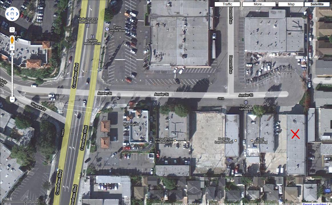
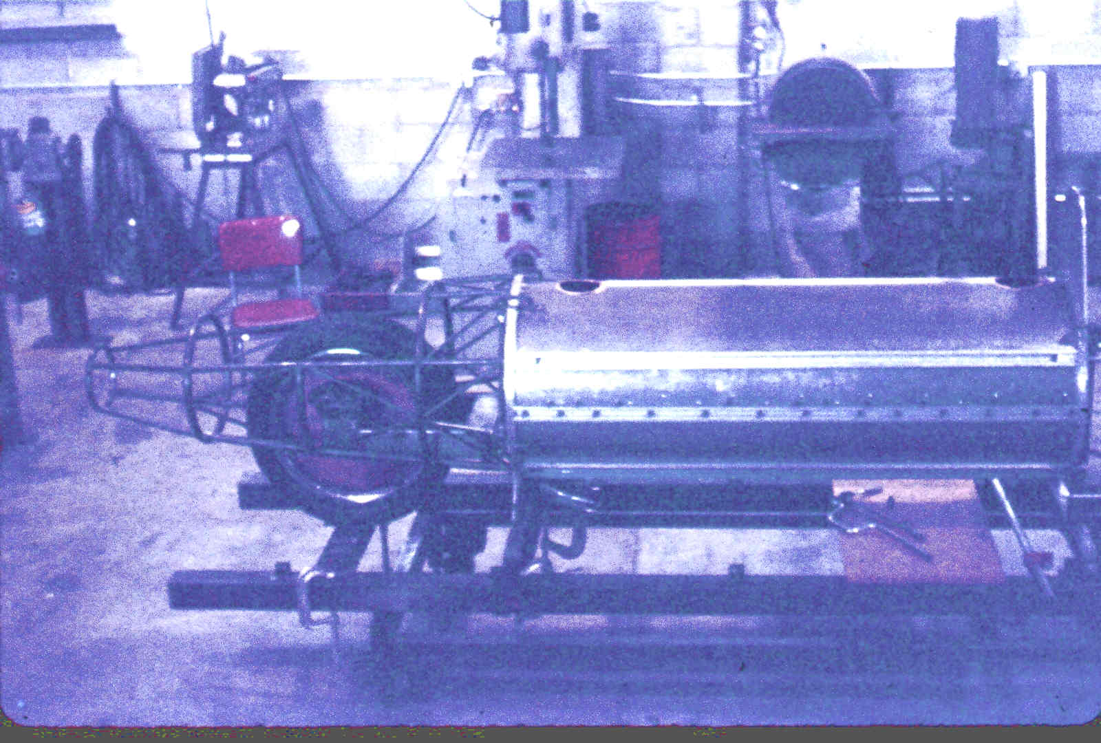
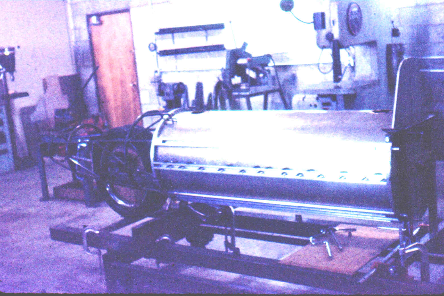
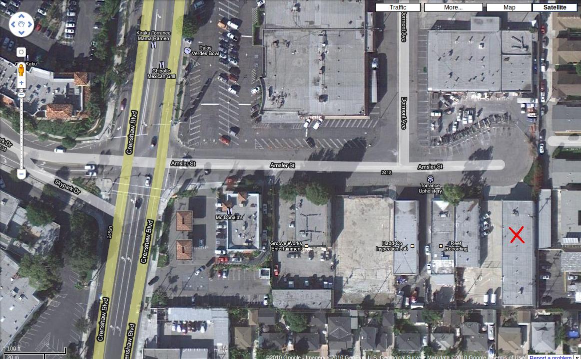
It was not built in Salt Lake City.
It was built in Torrance or Lomita California on Amsler street.
See the map. I know I drove there daily from my home in Hermosa Beach.
Paul Lamar
--
The Rotary Engine NewsLetter. Powered by Linux.
ACRE NL web site.
http://www.rotaryeng.net
Youtube key word PaulLamar2
Copyright 1998-2010 All world wide rights reserved.