Does anybody know how the wiring goes for the four individual coils on
the
Renesis engine. It is one of the test engines bought up by that
Australian a
couple of years ago.
There are three wires (black, black with white stripe and the third wire
is
a different color for each coil). The coils black wires are all wired
together with a 0.47uf capacitor attached at the splice, and the
black/white wires are also wired together but the wire coming out was
cut
off at the splice. -- Karibian
Black with white stripe is 12 volt power
The third wires are triggers from the computer
as follows.
G is green front rotor leading (lower) plug.
W is white front rotor trailing (top) plug.
Y/G yellow / green is back rotor leading plug.
B/O blue /orange is back rotor trailing plug.
Black is ground.
Paul Lamar
Keep the cap on the ground wires, too.
Kenny
These are inductive coils and they normally require a computer.
Inductive coils are turned on for a period of time and then
they fire when the current is suddenly turned off. This off time
is called dwell. If the dwell is too long the coils over heat.
If too short you don't get full spark energy.
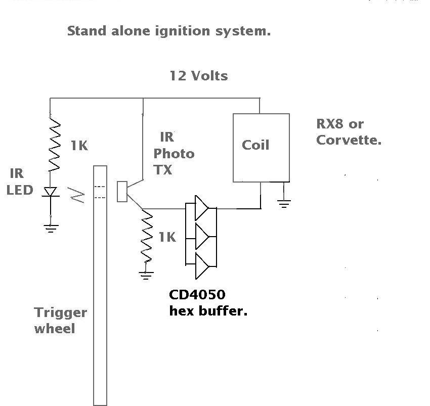
The breakthrough on how to make this stand alone and work without
a computer just occurred to me. The trick is to slot the trigger
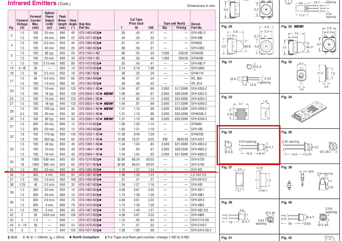
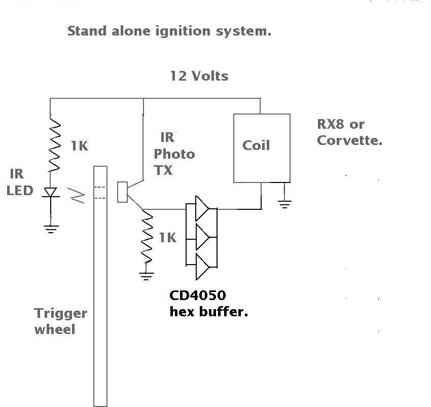
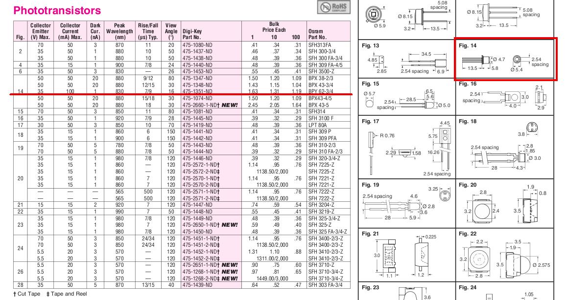
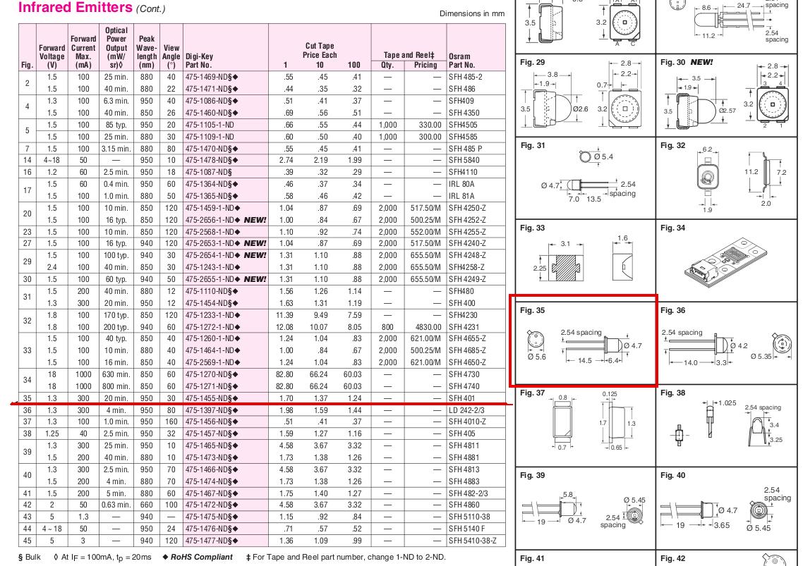
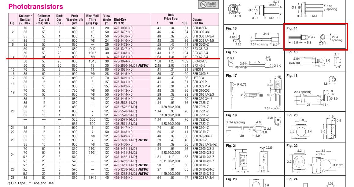
wheel and use a IR photo transistor, an IR emitter LED and FET switch
instead of a magnetic pickup or Hall Effect sensor. These devices
put out a single narrow pulse. Not what we need.
When the IR photo transistor sees the infra red emissions from the
IR LED it turns the coil current on using an high voltage FET solid
state
switch. I used something like this for years on my computerized
road test equipment and it is very reliable and durable.
It will work with just about any stock inductive plug on coil system
including the Corvette GM coils. The length of the slot controls the
dwell time. The end of the slot controls when the coil fires.
I have been thinking about this problem ever since the stand alone
coil on plug systems first appeared. How do we get rid of
the computer?
If you want to fire the leading and trailing plugs at different
times you can use four slots with four photo TX's and four
LED's other wise each photo TX fires both leading and trailing
plug coils at the same time.
Now some of you electronic types might say "why not just
use a 555 one shot with a fixed pulse width to turn on
the current in the coil for a fixed period of time triggered
by a magnetic sensor or Hall Effect "?
The problem with that is the spark timing will vary with RPM.
You want the plugs to fire at 22 degrees TDC over a wide range of
RPM's so that approach will not work.
Basically this thing works like distributer points.
Paul Lamar
Paul,
Will this also work on a 2nd gen?
Any plans to make trigger wheels?
Can the trigger work with an EFI also?
Joe Berki
Limo EZ
It will work on any rotary engine. 2 rotor or 3 rotor.
(3 slots)
Here is a 50 cent improvement. A CMOS 4050 all six gates connected
in parallel drives the FET very reliably.
Paul Lamar
Paul,
Would it be better to mount the trigger wheel and the associated electronic
components off of the flexplate area assuming one uses Tracy"s PSRU? When
you loose a belt it could take out trigger wheel components. Just a
thought.
Joe Berki
Limo EZ
Yes that would work. BTW Joe I get a lot of bounces
from your email address. It would better if you got a new
email address.
---------------------------------------------------
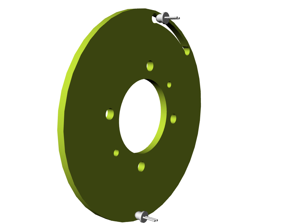
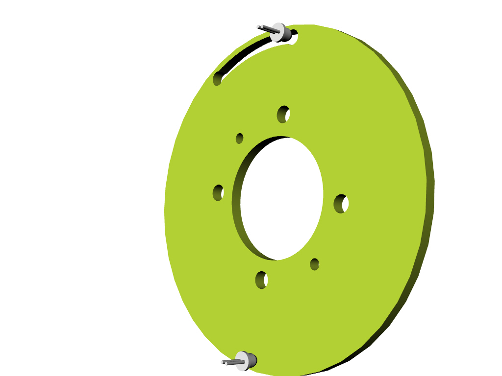
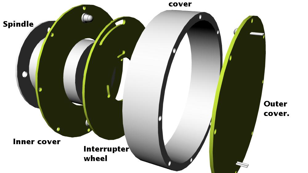
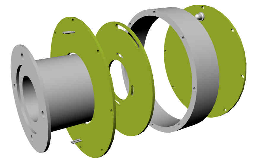
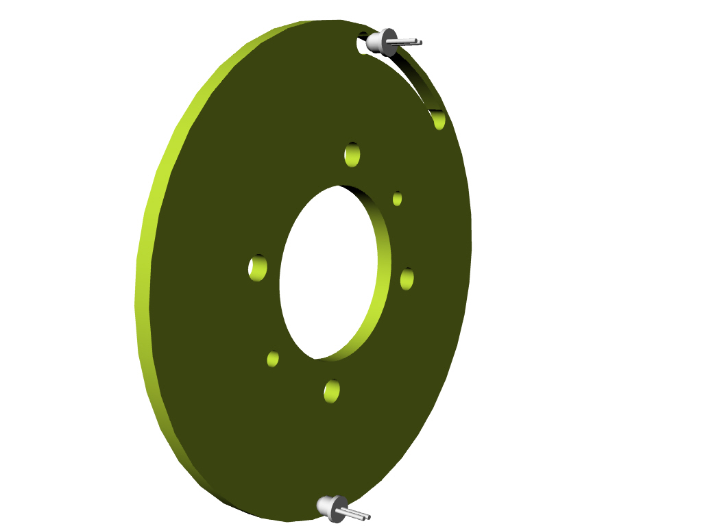
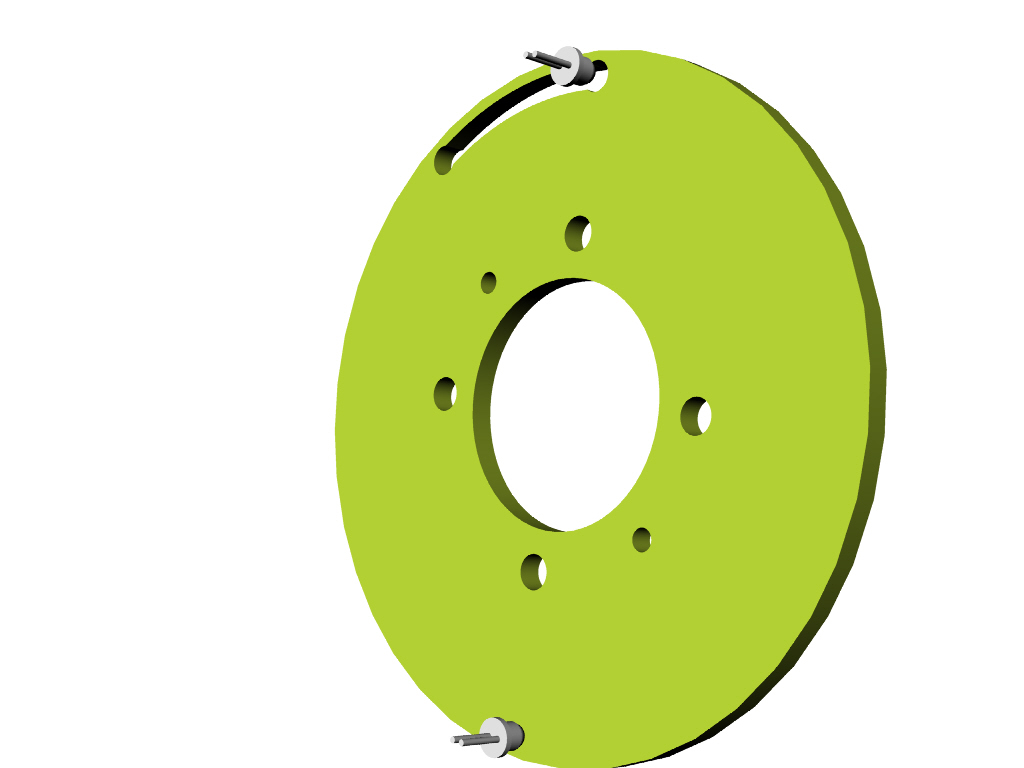
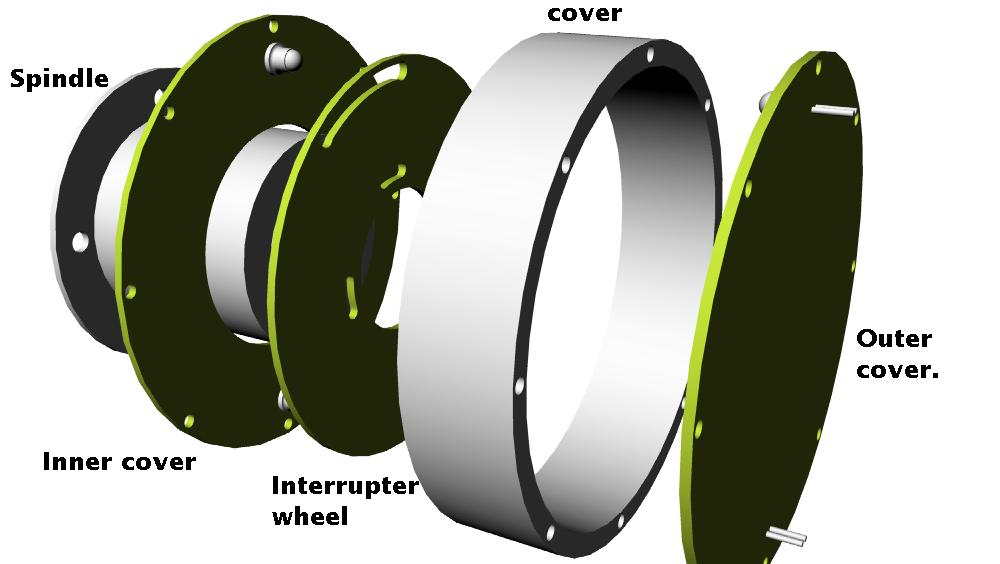
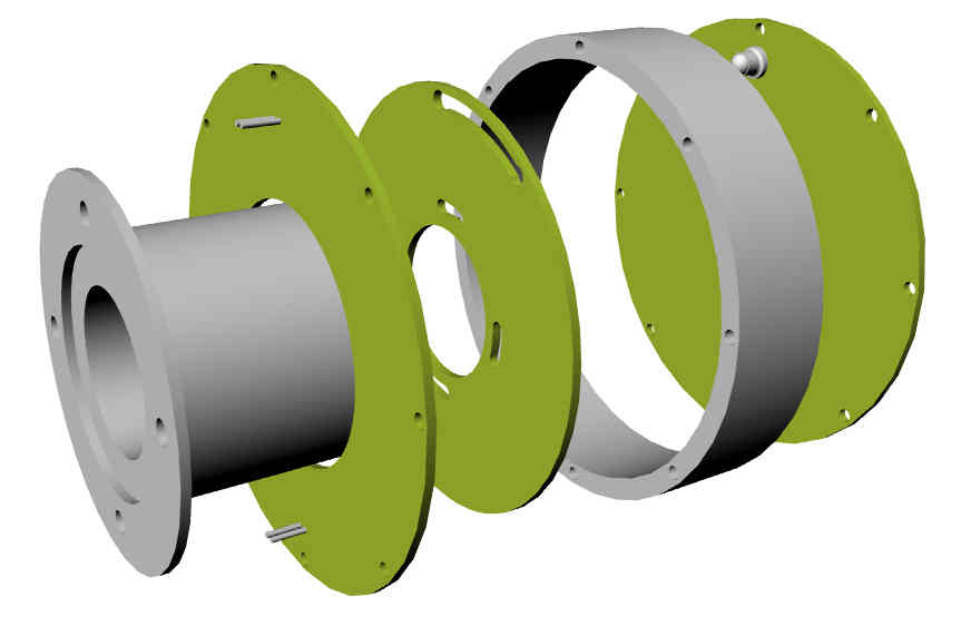
Here is what the cover would look like. It is about 4.25 inches
in over all diameter. The front cover, the rear cover and the
trigger wheel are made from 1/16th fiberglass. The small amount of circuitry
needed is etched on the front cover. The spindle will work
with several types of ignition systems.
Is anybody interested in buying one of these? I'll have some made.
It will work well with a Holley 2 barrel carb for low overall all
P-port engine cost and simplicity.
Paul Lamar
I'm interested in any thing that has been tested sucessfully on a real motor in
our operating band of ~1500 to 7,500 RPM.
C. Smith
OK I'll keep that in mind if we get some more interest to the point
of testing it on the dyno at $650 a day :) However the economics
does not look good at this point in time.
Paul Lamar
I don't care about a lab dyno, just see it running. A video with a tach, or
maybe the Hy-tek Daq. Just to see that it works.
C. Smith
I don't understand why you are skeptical :) I have built well over 100 of
these photo interrupter circuits used on my computerized test equipment
starting back in 1976 or so. Not rocket science.
Some bought by Ford from me :) I guarantee it to work or double
your money back. The frequency out of the photo circuit is only
133 Hertz or CPS. The response of the photo TX is 9 microseconds!
The road test system was used to measure the acceleration of the
Voyager around the world un-refueled. At 150 fps second the photo
interrupter was putting out 15,000 CPS in the road test system.
100 pulses per foot.
The ignition system is a piece of cake by comparison :)
http://www.rotaryeng.net/RT1.pdf
http://www.rotaryeng.net/IEEE-road-test-sys.pdf
http://www.rotaryeng.net/id-pad-C&D.pdf
I'll have one spindle that bolts to the front pulley built by a machinist friend.
The rest of it can can kludged up for a test if somebody has a running engine.
Do we have any volunteers with a running engine to test it?
Paul Lamar
--
The Rotary Engine NewsLetter. Powered by Linux.
ACRE NL web site.
http://www.rotaryeng.net
Youtube key word PaulLamar2
Copyright 1998-2010 All world wide rights reserved.