If you want the simplest and probably the most reliable ignition
system
get a two cycle two cylinder small outboard ignition system.
Fires the same number of times and 180 degrees apart just like a
2 rotor.
As close as you will come to a A/C magneto.
http://www.iboats.com/
http://www.iboats.com/Johnson-Stators/dm/view_id.271367
http://www.cdielectronics.com/
Down load the complete catalog.
Some of these stators are as low as $20 used.
The high voltage coils supply 300 volts for a simple CD system
and the other coils may supply enough 12 volt current for an EFI
system. No belts. If the main electrical system or alternator
fails the engine still runs.
This stuff is mass produced in the millions and extremely reliable.
Paul Lamar
Some interesting stuff in that catalog. Some of us wouldn't know
exactly
what would comprise a complete system, as it looks like they are
all parts
of an upgrade for certain motors.
Did you notice the EFI and ECU units in the catalog? They also
note that
these can be reprogrammed for "racing purposes".
Would this be suitable for our purposes? Of course I don't think
it would
be
a good idea to mention aircraft. One could say I'm making a
marine rotary
conversion.
C. Smith
Good idea Craig. A racing rotary boat motor :)
All you need is a source of 300 volts, provided by the rotating
magnet
and stationary coil, a 1 ufd 300 volt cap and a switch of
some sort. An FET works fine and they are easy to use. Way back
about 30
years ago we discovered that a 50 cent CMOS CD4050 or a CD4049
chip makes
a great FET driver if most of the six gates in the chip are
connected in
parallel.
Since that times 1000's of FET gate drivers have been designed
and built selling for as much as $6 each and so far I have not
found one that works better than a CD4050. Many of them require
a regulated supply which lowers efficiency and cost more money
and parts.
I set up this simple CD circuit on the bench in half an hour with
a 300
volt DC power supply and it works great. The FET is a IRF740.
I am rapidly discovering it is all about the 300 volt power
supply. You
need a robust power supply that does not crap out when it is
shorted to ground
and that is where the charging coil in the outboard motor comes
into play.
Nothing could be simpler than a large magnet passing a coil to
rapidly
charge the 1 mfd cap.
Paul Lamar
--
So now I have more questions. Does one of these 2 cyl systems
have enough
juice to fire both plugs at the same time?
Can it be used for multi-spark, or would one need to stack 2 or
more with
abit of angular offset, then utilize your FET controller to
switch the
spark?
Last, maybe a failsafe contactor to switch out multispark in the
event of
a malfunction of computer to revert to stone axe mode? Or am I
making it
overly complicated?
C. Smith
I think stacking two would be needed. The charging coils are
available
stand alone and very cheap. All we need do is find the curved
magnets stand
alone. Jeff can make the rotating magnet holder. The electronics
are trivial
as I just demonstrated. Here is a picture of what the spark looks
like. The picture is a bit out of focus but you can see the spark.
Paul Lamar
K&J Magnetics makes custom magnets, $150 minimum order. I
wouldn't have
a clue as to the dimensions or polarization, but
I'll bet you do. Looks like a quote is free.
http://www.kjmagnetics.com/custom.asp
C. Smith
One of my hangar neighbors fixes Mercury's. I can get the dims
of one of those flywheels. Probably not for a week as I have
to go to PA on biz next week.
Paul Lamar
Check out the last five magnets at the bottom of this page.
http://www.kjmagnetics.com/products.asp?cat=168
A the very least, it demonstrates it is doable.
C. Smith
Looks too small. We need something 3 inch radius
or larger. Some of these big ones are high bucks.
Paul Lamar
Every Day Practical Electronics mag just published
another article by my favorite world wide ignition
engineer. Namely Australian John Clarke.
www.epemag.com The subject was "Replacement Module for
small petrol motors". Page 12
Here are a couple of pictures of a used outboard motor flywheel
I bought for $10 in an outboard engine repair shop. I wanted
the magnets out of it.
Also some more or less self explanatory Figures from the mag
article.
Paul Lamar
Could something like this be incorporated into the flex plate?
Tracy's PSRU
seems to have a lot of open area to route wiring out to the
electronics.
Joe Berki
Limo EZ
Certainly could fit in that area. Ideal for use with a carb.
Paul Lamar
Hi Paul,
I took your advice and purchased an old 13b for tear down and
familiarization purposes. I also purchased Tracy's book and
read it cover to cover 4 times (I learn a little more each time
I read it).
I want to start off sort of in Tracy's footsteps by using carbs.
I have two Johnson / Evinrude 2 barrel carbs that I will
fabricate onto an intake manifold, but I keep getting hung up on
the ignition side. I think the idea of using an outboard
ignition system is the way to go for me. I have electrical
schematics for my 1973 Johnson that I can scan and send if it
would help with this thread. The main components would be
stator, spark advance mechanism, power pack, flywheel with
embedded magnets and coils.
My only question is that on the Johnson, spark advance is
controlled by the spark advance mechanism via a direct
connection to the throttle. Would we need to incorporate this
into the design for a/c use or is there a different way of
overcoming the spark advance problem?
Franklin
How much HP did the Johnson carbs develop?
To work it should be around 200 to 250 HP.
In other words what is the carb throat inside diameter?
You will need about 3 square inches per carb.
Do you plan to p-port?
http://www.rotaryeng.net/fund-of-intake.html
P-ports are worth it as the intake manifold becomes
trivial to fabricate.
Do you have access to a lathe?
You will need it to make a rotating magnet holder for the
front of the e-shaft. I have a fellow that can make
that part for you if necessary.
Yes by all means scan the Johnson electrical schematics.
That will help when buying parts for the ignition.
Don't worry about ignition advance. Just run the engine
at 22 BTDC fixed. Aircraft engines like boat engines
cruise at one RPM.
Paul Lamar
Paul,
How about a dual ignition systems? Assume coil-on-plugs design
and that we would use a two stroke marine engine magneto and
coils incorporated into the starter gear or torsion plate area
of the housing. Also assume we would have capacitor driven
ignition modules like the new solid state digital programmable
MSD, 6AL-2. Check them out. Small and compact. One for each
rotor.
First some givens about our rotary engines with the single
leading plug: The engine doesn't run very well on trailing
plugs alone, as quite a lot of the fuel goes out the exhaust and
is burned in the exhaust system. Said another way, with a two
rotor engine and a leading plug fouled, the exhaust system may
well overheat, or the engine would run rough enough that we
would want to shut it down after a short time. That means the
Achilles heel of the Mazda rotary is the leading plug. As
quite a few members have pointed out though, a spark plug is
pretty basic technology. Yes I agree but I also can't count
the number of times I have had them crap out on a 2 stroke oil
burning engines. Prudence would dictate changing them quite
regularly since it is a critical point of failure or beg Mazda
to cast us up some two bung leading plug housings.
Conversely if the trailing plugs fail the engine power only
reduces about 3% if that. So with a good leading plug and a
magneto system, the engine would continue to operate just fine.
BSFC will be a little off but we won't get our feet wet and the
plane can continue on for many many hours.
OK we can all agree that a magneto is basic technology and
very fail-safe. The magneto fires when a magnet passes by
coils set 180 degree (20Bs would need three spaced at 120
degrees) apart. These coils could be wound to produce 300
volts. Timing can be fixed for a cruise rpm.
Now for the plus alpha. The MSD ignition devices can be
programed to fire the leading (and trailing) plugs many times
and at moments when the magneto isn't doing that. Each MSD
power pack could get its signal to prepare for a firing
sequence from the magneto or modified coil voltage pulse. Since
the MSD devices have intelligence they can vary the timing with
rpms. and other inputs received from sensors or even a
MEGASQUIRT engine control board.
The question is, How do we isolate the MSD power from the
magneto power because they are both hooked up to the same coil?
Diodes are the easy answer but I wonder if that is a robust
solution? In the scenario above power unit could be charging
the leading plug coil.
A FET switch might be an answer but the fail safe would have
to allow the magneto to continue firing the leading plug coil
FETs on the two MSD outputs to the leading and trailing plugs
would allow split timing if necessary at the higher rpms. For
instance the magneto fires the first burst on the leading plug,
followed immediately by two stronger pulses from the MSD
Capacitor while perhaps a third pulse from the MSD is directed
only to the trailing plug.
Your thoughts?
Doug in Japan
I think you are making a mountain out of a mole hill here Doug.
A phenomena call sag happens when the plugs get to be about 50
hours
old or so. Minor loss of power.
The solution is put in new plugs on a regular basis. The plugs
catch
hell in a rotary as they spark twice as often as a 4 cycle piston
engine. The same as a two stroke. Now this has been reported with
inductive type ignition only but as far as I know nobody is using
a CD
system in a flying aircraft. CD systems have a proven track record
of making plugs last longer in piston engines.
No telling what the CD spark plug life would be in a rotary
until we
get some good data. The MSD ignition apparently only fires more
than
once up to some RPM which I know not. I have talked to their
engineers
about it and they don't seem to understand the rotary so they
cannot
give me a good answer. One MSD system per plug would give a lot of
redundancy.
We don't have any data running on trailing plugs
alone for a period of time so it is hard to say what will happen.
Ignition failures of any kind are rather rare with the possible
exception of 2nd gen igniter ballast resistors which can be traced
to continuous high RPM use. The wattage rating of these resistors
must be increased.
Tracy also had problems with early Corvette
coils over heating but I suspect that was caused by excessive
dwell and the fact they were being triggered twice as often.
One unknown is the charging coil in an outboard motor may not be
able to charge more than one capacitor at a time so the outboard
type ignition system may require two magnets, two capacitors and
two charging coils per rotor for firing both leading and trailing
coils. Some experiments need to be made to check and see if this
is true.
You will also need outboard type CD coils as RX8 or Corvette
coils per plug will not work with CD systems.
The thing about 2 cycle outboard coils is they are designed
to run at high RPM and CD systems are actually easier on coils.
They become mere pulse transformers and not a device to
store energy. In that case they should be far more reliable
Paul Lamar
Hello Paul,
Attached please find the wiring diagram for a 1977 V4 2 cycle 85
HP outboard. I do believe the stator and circuitry is more
complex than the application we are looking for due in part that
it is working 4 cylinders instead of two. If perhaps someone
had a wiring diagram of a 2 cylinder 2cycle outboard it would be
even better.
With regards to the throat diameter of the carbs I was
considering, I was going to use Tracy's estimate of 1 square
inch per 50 horsepower. Is that in the ball park or should I go
larger? I have not thought about a P-Port yet as I'm still
learning and the thought of taking a grinder to the engine is,
at this point, beyond my ability.
Regards,
FranklinHello Paul,
Attached please find the wiring diagram for a 1977 V4 2 cycle 85
HP outboard. I do believe the stator and circuitry is more
complex than the application we are looking for due in part that
it is working 4 cylinders instead of two. If perhaps someone
had a wiring diagram of a 2 cylinder 2cycle outboard it would be
even better.
With regards to the throat diameter of the carbs I was
considering, I was going to use Tracy's estimate of 1 square
inch per 50 horsepower. Is that in the ball park or should I go
larger? I have not thought about a P-Port yet as I'm still
learning and the thought of taking a grinder to the engine is,
at this point, beyond my ability.
Regards,
Franklin
Nothing was attached Franklin. Try again.
1 square inch is on the small side for 50 HP. 1 square inch
is more like 45 HP
Jeff can do the p-port thing for you.
jeff.doddridge@gmail.com
A lot easier than making a manifold however you must
be willing to disassemble and reassemble your engine.
Mazdatrix will also build a P-port engine for you with
Jeff's modified p-port rotor housings.
Since you are using carbs you won't need the slide throttle.
Read this.
http://www.rotaryeng.net/intake.html
If you still want to use a side port a lot depends on how
much room you have under the cowl when building manifolds.
What kind of airplane are you building?
Is your engine a 4 port or six port?
Are you good at tig welding aluminum? Steel welding?
Steel tubing is the easiest to use as the welding skills
required are minimal.
Here is a trick for the transition of round tubing
to oval intake ports. Don't try to flatten a round
tube. The area will be much reduced which will seriously
affect the HP you get. We have been all over this in years
past. A lot of people have been disappointed in the results
when building side port manifolds.
Paul Lamar
Let me try the attachment again.
Regards,
Franklin
There seems to be enough parts for a two rotor but they
must be rearranged. I am not sure as there is no picture of
the flywheel showing the position of the charging coils
and firing coils. Do you have a digital camera or a cellphone
with camera?
BTW I just found a source for magnets. This is a major
breakthrough for us.
http://www.maxrules.com/fixomccdi11.html#MAGNET
I can now go wild designing a magnet holder which is the key
to the whole works.
Paul Lamar
Attached are pictures of the flywheel from the Johnson. As you
can see there are sets of magnets embedded into the flywheel and
then machined smooth. There are 6 sets of magnets or 12 magnets
all together. I'm not certain but I do believe that the sets
are opposite in polarity. I'm fairly certain I read that
somewhere.
I'm planning on building an aerocanard and I'm trying to keep it
as simple as possible. Don't believe I will be able to do the
gravity feed fuel system, so I'll have to go redundant on the
low pressure fuel pumps.
Franklin Canosa
Lots of magnets in there. I think I have found a picture of
what goes with it which I included. Do those look familiar?
The two light colored coils are the charging coils for the
CD ignition. The other two are the generator coils.
The big challenge now is making a light weight holder for all
those magnets that will fit the e-shaft. Do you have a friend
with a lathe? You will get an alternator out of the deal.
Paul Lamar
Paul,
Yes those are part of the CD system. The blue ring device is the
'spark advance mechanism' that we can probalby do without as you
suggested we just time the engine to 22 BTDC. The stator is
correct and you are correct (I believe) about the different coil
purposes.
I don't have direct access to a lathe, but would be willing to
send down the parts from my old outboard for experimentation
purposes. I still have the stator, flywheel, a couple of good
coils and perhaps even the power pack. I was going to try and
sell them on ebay, but I would probably get 10 bucks for the lot,
and this is a far more fun and useful application of the parts.
Let me know your thoughts.
Franklin
I would like to take a close look at that flywheel.
Most of the other parts are interchangeably or can be bought
used or new.
I would like to put it in a lathe can cut it down
to drastically cut the weight and then make an aluminum
hub for it to fit the flange on the e-shaft. The flywheel
aspects of it are not needed and in fact it is not good
to add rotational inertia to the front end of the e-shaft.
This. I think, is the key to making this system practical.
With the flywheel I have all I need do is drill out
the rivets to remove the magnets. I can then mount
them in an aluminum hub.
Paul Lamar
Paul it may be simpler than that. Machine the outboard flywheel
to fit under
the damper, machine it lite and use as is. a stupid suggestion by
milo!
I'll investigate that option shortly. I have one of Tracy's
dampers sitting right here.
-------------------------------
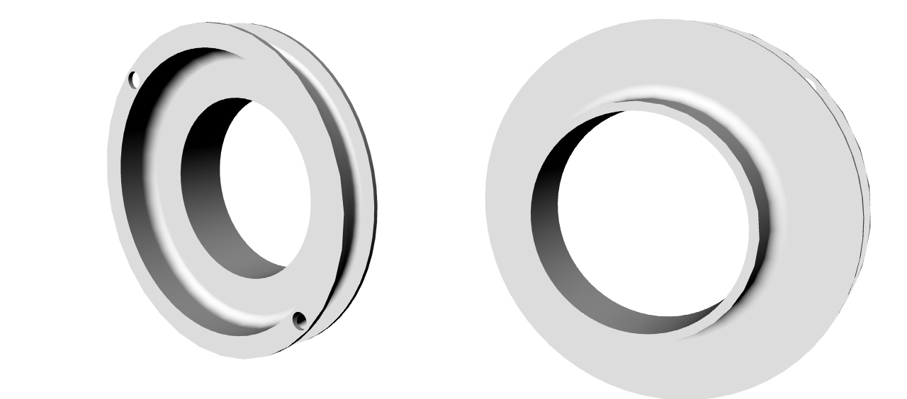
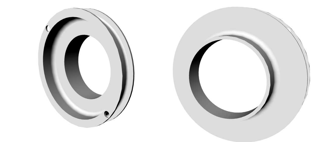
Here is what I have so far. I just had an idea this morning
on how to make this a bit cheaper and better.
If I chuck the front hub with
the bolted on pulley in the lathe I can take an small internal
cut out out of the steel pulley to insure it is concentric.
Then press in something that looks like this.
The groove will be filled with uni carbon to cut
the rotational inertia and increase the burst strength.
Important at 7500 RPM.
Paul Lamar
--
The Rotary Engine NewsLetter. Powered by Linux.
ACRE NL web site.
http://www.rotaryeng.net
Youtube key word PaulLamar2
Copyright 1998-2010 All world wide rights reserved.