That is looking a lot better Jean.
Make sure the prop flange is the same as one of
these SAE standards. The big one is for wood props
and the smaller one for CS props.
Paul Lamar
I PAUL
I FOLLOW YOUR RECOMMENDATION TO DESIGN WITH NEEDLE BEARINGS
AND I CAME UP PRETTY GOOD BUT I NEED YOU TO LOOK AT IT AND
COME BACK WITH YOUR RECOMMENDATIONS.
I AM SENDING YOU 3 2SHEETS WITH DIMENSIONS
Jean Prudhomme
If your drawing program can export IGES or AutoCad DXF files send me
those
instead so I can import them into Rhino. STP (STEP) files also work.
It is best to send the individual part drawings with dimensions rather
than dimensions on the complete assembly. Too confusing.
I don't need the part drawings on the Ford planetary parts
as I have those in Rhino dwgs already.
Once you have it in Rhino you don't need to send dimension
at all. All you need send is the Rhino 3DM file.
Paul Lamar
Paul all the file are in IGES and i try to transfer to george Grimes
and he can open it.
I still working on the full design and i added a snap ring on the
front to hold the front seal,i will have to use 2 check valves to
prevent the high pressure to interfer with the low oil pressure.
I should start to design the separate parts soon and i will forward to
you
Jean Prudhomme
Here is a preliminary Rhino rendering. It will take a lot more
work. The prop flange spline may not be accurate. How many
spline teeth are you planning on Jean? It is also not clear how
you are going to retain the flange on the spline.
Paul Lamar
Good afternoon Paul
The flange will be secure between the bolt,s flange and the
reset on mainshaft, i am looking to add a small portion of taper
at the end of the flange and the shaft for a better tight fit
when main bolt will be torque, a special shaft with same spline
as the planet to be machined and will be welded to a steel flat
bar as a tool to hold the shaft at the moment to torque the prop
flange bolt
I added a snap ring at the front to prevent the seal to coming
out.
I know your idea to machine the front planet and attached to the
inside flange flange shaft ,but my point of view it will be less
machine work and cost to machine the whole planet with the shaft
and it will be easier to mount the planet gears and will be
stronger and it will be one pce for lateral movement.
For machining it can be first drill sideway at each gear close
to the size and be finish with small end mill bits
,those gears shaft head can be pressure fit without driss pin
secure .
Just an idea.
With my design it will be less expensive and easier to replace
the planet ,the inside flange can have pins with the planet
surface to increase the strenght, it,s already 6 holes of .250
for more oil feeding but can be use for pins between the shaft
flange and planet
Jean Prudhomme
Here is what it would look like with a housing made
from thick wall tube and plate instead of the mini sprint bell.
There are two tube sizes needed. Four inch dia. 1/2 inch wall
and six inch dia. one inch wall. The four inch can be bored
out of bar stock as I found a shop in SZP with a really big old
lathe than can drill 3 inch dia. holes in 4 inch dia. bar stock in
one operation. You weld everything together and then machine it
to final dimensions like Don Dunbar did on his gear box.
Don'3 was a bit over kill as far as thickness's were
concerned. I also don't think the webs are required but
they can be welded in with no trouble.
This would be better than the mini sprint bell as the 6" dia. section
that holds the ring gear can be made long enough to accommodate
all the thrust bearings required. Just like Tracy's box.
Also it will fit Jeff's stock motor plate.
Paul Lamar
Paul, I have a couple cast housing, 6061 T6 like in picture 6 from an old
experiment that i will send if you like. Give me the dimensions and I
will
measure them up. no charge.
milo
Thanks Milo
That one is about 5 inches long and six inches in diameter.
I'll send you a shipping address by private email.
-------------------------------------------------
I got it Milo thanks. How many castings do you have?
I think we can design a box around it.
ID is about 3 inches and OD at the mount end is 5 inches.
BTW when are you heading for Texas?
Paul Lamar
Paul,
We only have two of those castings left if you need more our patterns are
at
precision casting in tacoma and one can order through them if interested.
Do
you want the other 2?
We will leave here on the 19th plan to be at your place before noon on
the
20th. Been packing the test stand today, bigger job than I thought,
almost done.
milo
Sure. Drop them off somebody may find a home for them.
Paul Lamar
Paul I try to export my design in IGES file which it show but it said it
can
export on that file and i said: the save operation cannot be completed
since
topology data is unavailable"
I sent you the last corrections and i will start to details all parts.
I already send you an estimated prices for bearings and seals
Jean Prudhomme
Jean,
I love It,
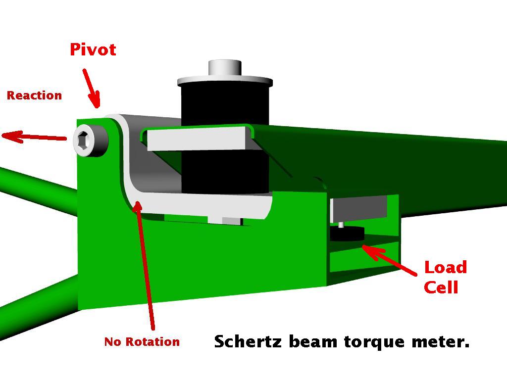
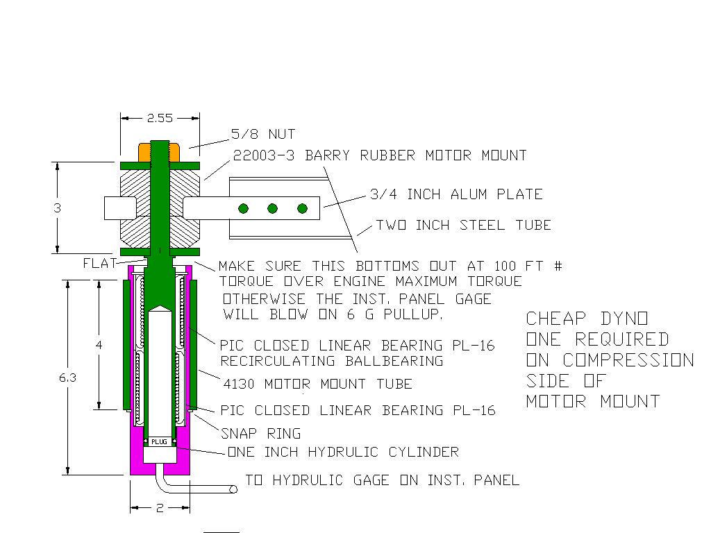
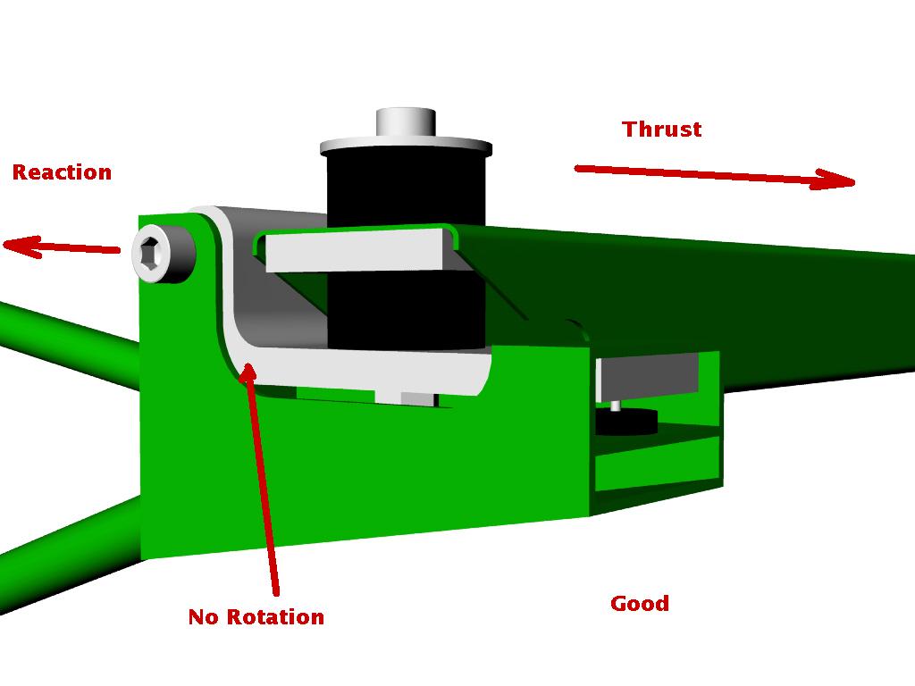
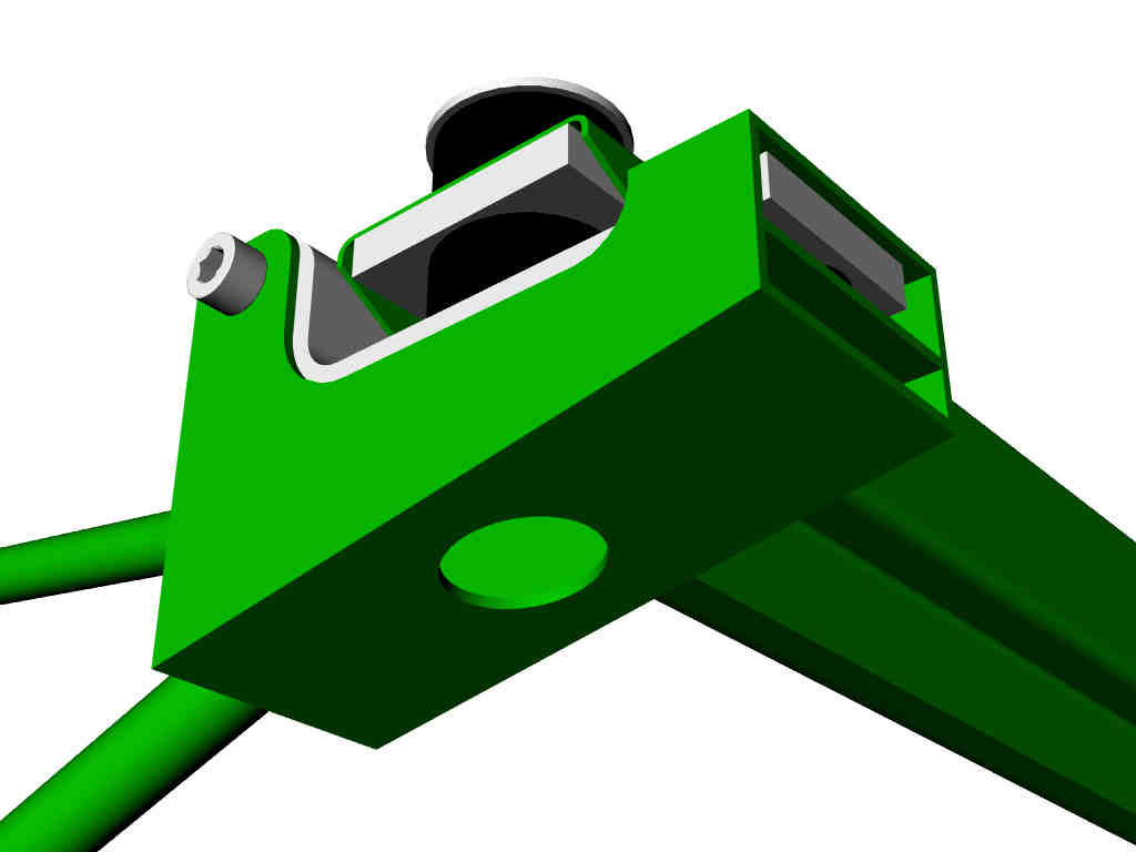
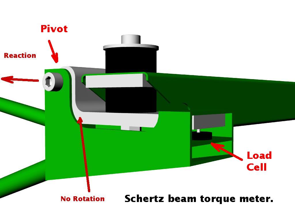
Perhaps we can get Paul to finalize his torque system to go into your box.
I digress a little.
Paul,Your water manometer reminded to bring up a point that has been
discussed before reference a torque indicator(HP gage).
Perhaps we are missing the boat by not putting a torque gage in every
airframe, that way every airframe becomes a test stand. We may be missing a
lot of basic data because of the lack of a primary indicator for engine
power and performance. Sorry to change the subject.
milo
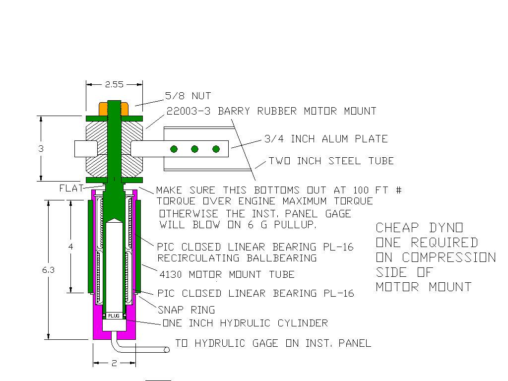
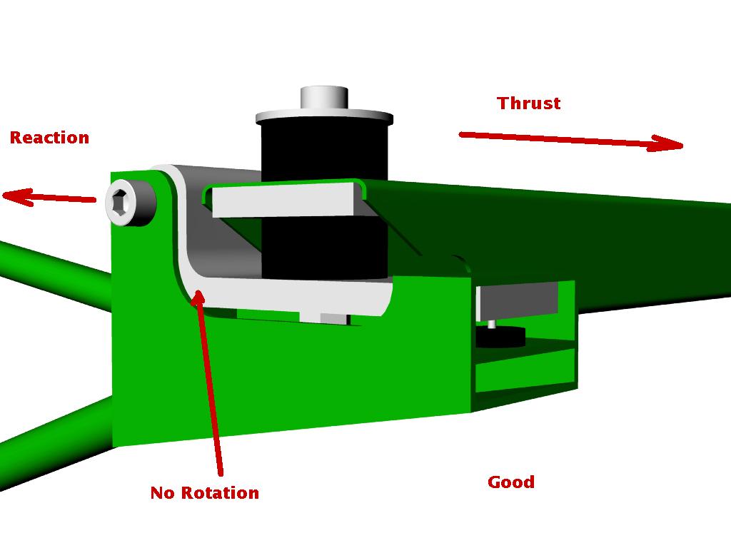
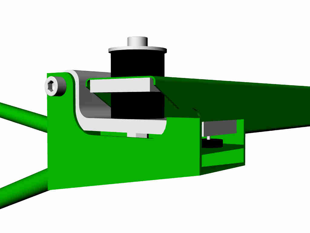
I am for that. It can be built into the motor mount.
Paul Lamar
--
The Rotary Engine NewsLetter. Powered by Linux.
ACRE NL web site.
http://www.rotaryeng.net
Youtube key word PaulLamar2
Copyright 1998-2010 All world wide rights reserved.