I went up today for a few laps at 3000 over Paine Field. The engine ran well
below the staging point, but started stumbling when above the staging point. It
ran smoothly through the staging transition on the ground, but when in the air I
could not tell by the mixture monitor if it was lean or rich. I tried leaning it
out and richening it up, but results were inconclusive so I stayed below the
staging point for the remainder of the flight. I'll tune it in flight when I can
get higher. Temps were down around 130 degrees at 4800 RPM and 110 mph, MP was
not noted.
I accidentally hit the cold start switch while on downwind with two other planes
ahead of me, and the tower told me to go around on final with the engine
stumbling badly, but the plane ahead turned off onto the taxiway just in time so
I told the tower that I would really like to land, so they cleared me.I still
had 7000 feet of runway ahead of me. The engine died as I turned off onto the
taxiway and then I noticed the cold start switch. The first order of business
was making and installing a switch guard for the cold start switch. I'm also
going to pre-load the switch with a rubber band so it stays in the off position
unless I'm pushing it on, and can just pull the rubber band off of it if I need
to shut down a set of injectors and run the remaining injectors on cold
start.(limp home mode for failed injector.)
The fuel self transferring issue was resolved by installing manual valve on the
transfer line between the tanks.
Brian Trubee
Dave Leonard had an off airport landing because of that cold start switch.
One can get a flip up guard that covers the switch to prevent inadvertent
operation.
"The fuel self transferring issue was resolved by installing manual valve on the
transfer line between the tanks."
Are you sure about that Brian?
Did you notice the fuel pressure when the engine starting running rough?
Could be you sealed the right tank when you closed the transfer valve.
I suspect the right tank vent is not working.
Paul Lamar
The right tank vent is working- I put a piece of tubing over the tank vent,
opened up the tank fill, put my ear to it and blew into the tubing- heard the
air going into the tank.
But yes- I didn't check the fuel pressure at the staging point, that's a good
point, and it's on my to-do list.
Also- to everyone out there running the EM2- what do you have for calibration
settings for your manifold pressure- what values do you have for scale factor,
low end offset, etc? I screwed around with mine and need to get it back to where
it should be. Between all those variables, I'm having a hard time figuring out
what all these values are supposed to be.
Any help here would be appreciated.
Brian Trubee
Brian
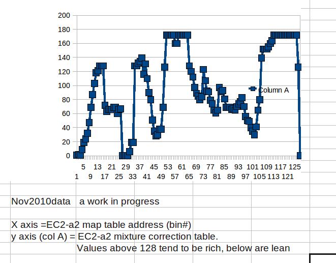
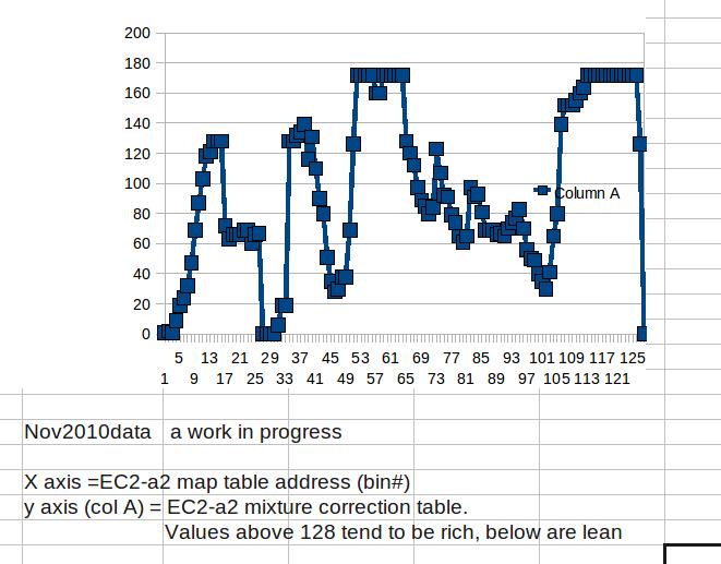
The map data that i finally wound up with after 250 hrs is on the attachment.
John Prendergast
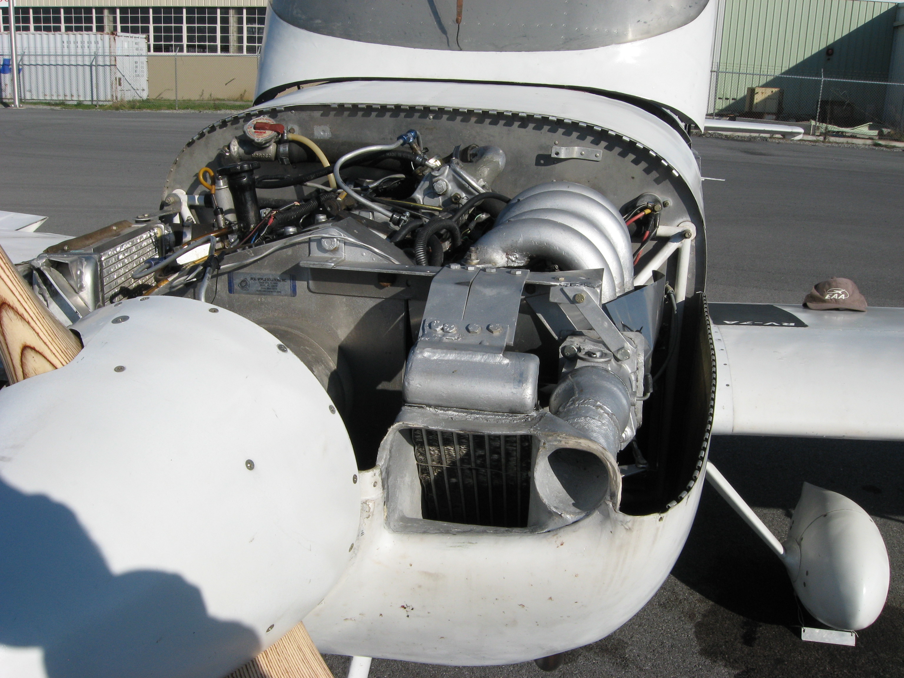
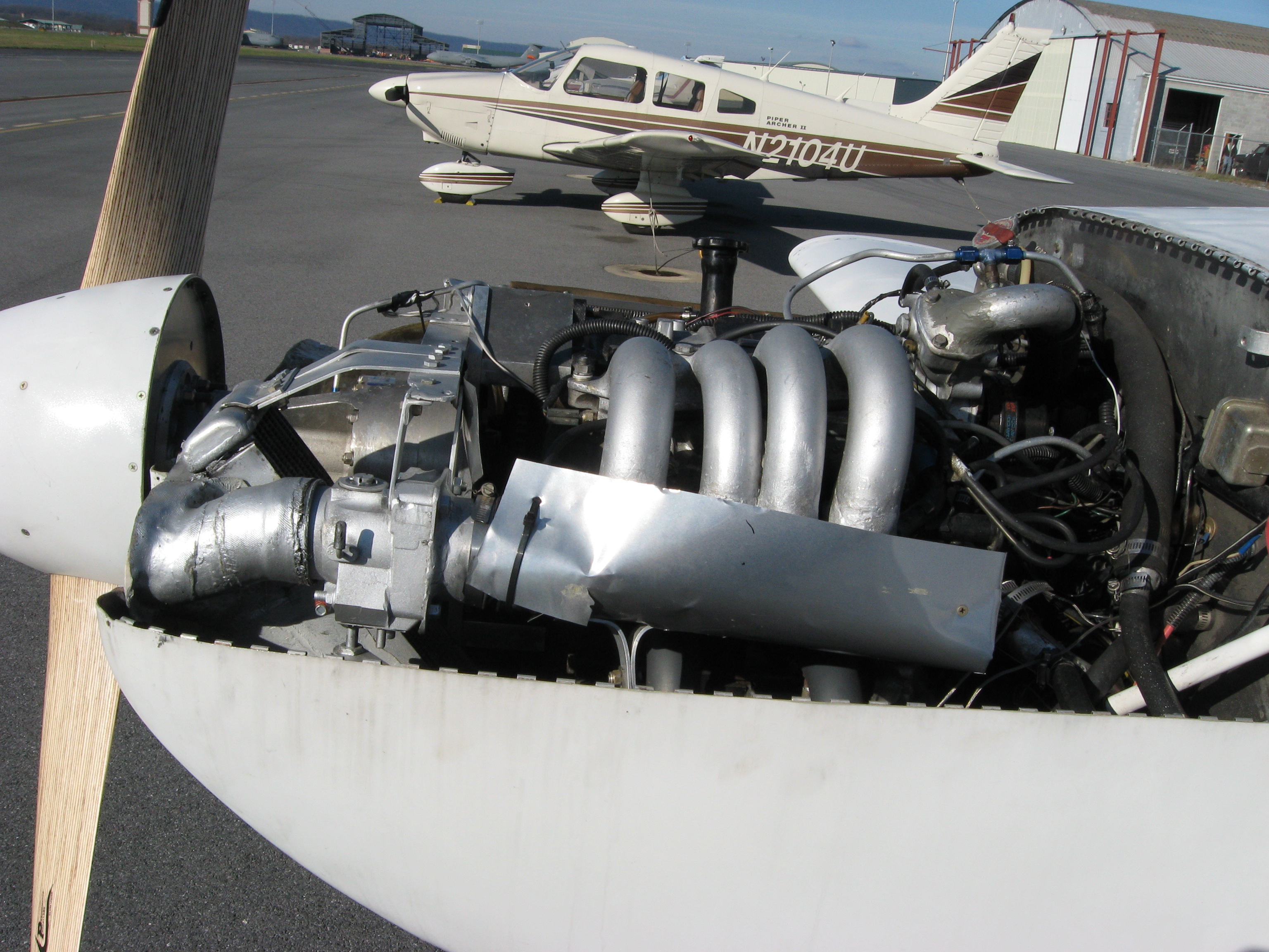
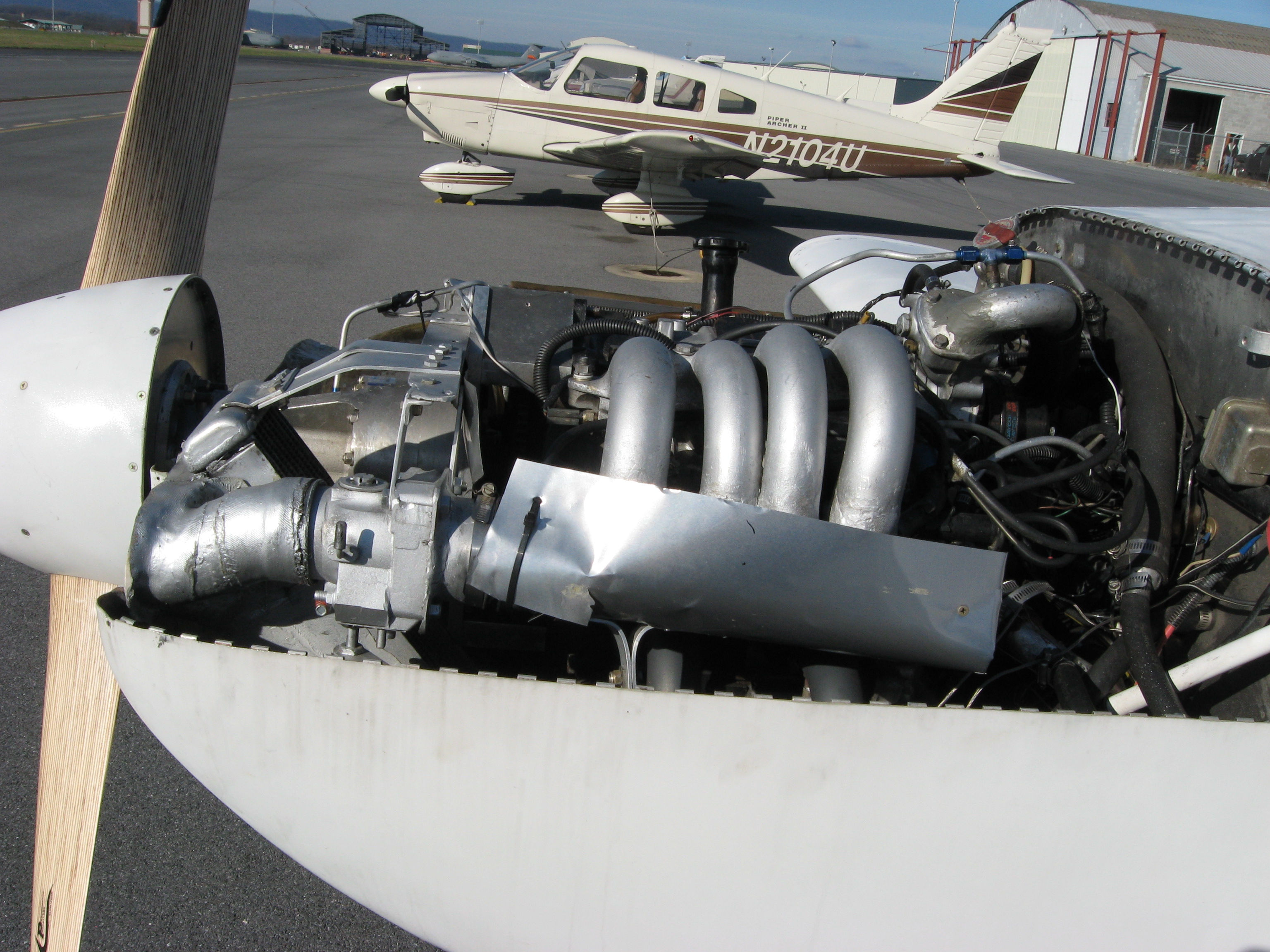
Got any pictures of your intake plenum John?
Where is the pressure tap located in that plenum?
Paul Lamar
Paul,
Tried sending a 1.6 mb photo but a message keeps saying that either it cant
find or will send as a 0 byte file.
Pressure tap is between throttle body and plenum.
John Prendergast
I should have no trouble on this end with 1.5 meg.
I am not sure what is going one yet.
Try sending that jpg again. If that does not work and
if you have photo shop it can be scaled down.
If not try downloading this free photo software and scale it down
with that.
http://graphicssoft.about.com/od/freesoftware/fr/photoscape.htm
Also if you have the raw data for that graph or the (xls file
is best) please send that.
From the looks of the graph you sent there is wide variations
in the amount of air actually getting in the engine at different throttle
openings. I assume the axis is intake manifold pressure.
There should be minor mixture variations but not such wide variations
with such small changes in manifold pressure. In other words
the air getting in the engine should be directly proportionals
to intake manifold absolute pressure. Obviously this is not
happening.
Milo is loaning me an engine with a side port intake manifold
so I will be able to study the pressure variations in a typical
plenum.
Has Tracy ever told you when he samples the intake manifold
pressure relative to the e-shaft TDC?
This is a question for everybody that is using Tracy's EFI system.
That will effect the pressure pulses in the plenum.
Thanks
Paul Lamar
Paul
The 2 Attachments are the only ones I have right now of the manifold. Pressure
tap is between the throttle body and plenum. The map data attachment has the raw
data downloaded from the EC2--a2 and a graph. I have labeled the axis which
shows bin # vs fuel correction data stored in the ec2.
On the ec2-a2 revision Tracy has revised low rpm below 2500 settings to use only
rpm to determine map table address vs relative fuel values. Manifold pressure
comes back into play above 2500 rpm. p27 of his revised manual describes the
address assignments.
I have not asked Tracy about where he samples the manifold pressure vs tdc. I
thought the response time of the intake pressure sensor tubing would lag so much
that it would not be able to correlate with the tdc of the engine and if placed
far enough away from the impulses it would send a constant pressure readout for
each throttle setting.
John Prendergast
Right! Sorry I missed the significance of raw data in the first
column. I don't do spread sheets that often any more :)
True I can't see much of the plenum. What I'll do when I get
set up is take pressure readings in three or four places along
the plenum 1000 times a second to get a handle on the turbulence
inside there. We were able to do that with Mark Supinski's airplane
with long tubes connected to each intake runner close to the
end housings. We could see the pulses change over a wide range
of RPM.
http://www.rotaryeng.net/fund-of-intake.html
What you might try is a manifold pressure accumulator made from
PVC pipe. That works well on our race car. Al Geitzen did
something similar on his 3 rotor powered velocity with good
results.
Paul Lamar
--
The Rotary Engine NewsLetter. Powered by Linux.
ACRE NL web site.
http://www.rotaryeng.net
Youtube key word PaulLamar2
Copyright 1998-2010 All world wide rights reserved.