Paul
Thank you for the photos of the single rotor
e-shaft. Are there any
dimensioned sketches available? I want to make a
drawing for my
machinist. I can back most of the details out of the
twin e-shaft if I
knew the width of the single eccentric.
I found an interesting cooling detail using a
expansion chamber for
the coolant overflow. Is this more complicated
than it needs to be?
Th elowest portion of the page below.
http://www.canardaviation.com/cozy/chap23i.htm
Matt Naiva
Here is an Autocad dwg from George Grimes I think.
What drawing program are you using?
Paul Lamar
Paul
Thank you! I will likely use Pro-E although the machinist
would likely
prefer a dxf file. I was reviewing the exploded drawings
on the
following link. There appears to be some sort of a counter
weight on
the flywheel end. Are there any special balancing
requirements for the
single rotor?
http://www.rotorparts.co.za/Info.html
Matt Naiva
It is kind of tricky to design counter weights for a one
rotor.
I think Pro -E will give you the centroid of a solid
which
might help.
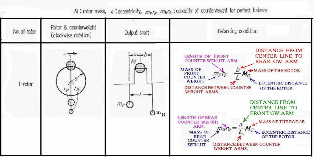
Here are the mathematical formulas for balancing.
Paul Lamar
The formulas above work pretty well. I used those for
calculating the
correction on the front counter weight, and designing the
fly wheel There
was very little correction to be made on the dynamic
balancer. I did that on
two sets with the same results.
Richard Sohn
N2071U
Paul,
This balance diagram is the uncorrected one with the rear mass mislabeled on the
one rotor portion.
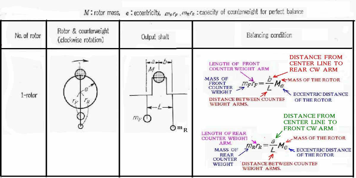
Dan Stanzione
Here is the corrected version.
Paul Lamar
--
The Rotary Engine NewsLetter. Powered by Linux.
ACRE NL web site.
http://www.rotaryeng.net
Youtube key word PaulLamar2
Copyright 1998-2010 All world wide rights reserved.