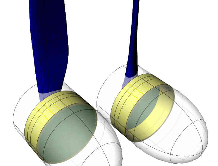
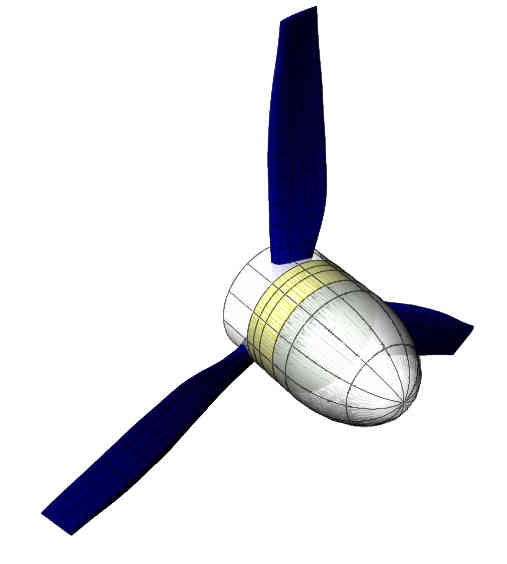
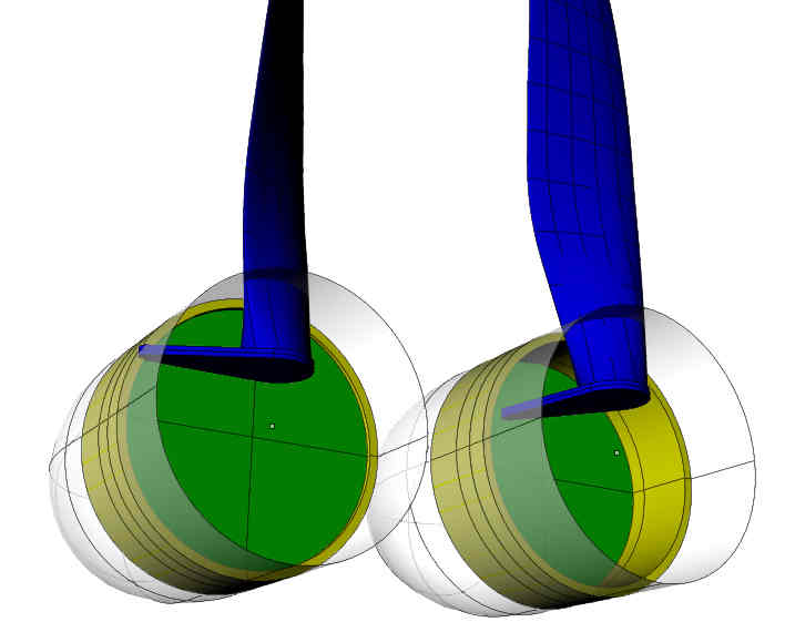
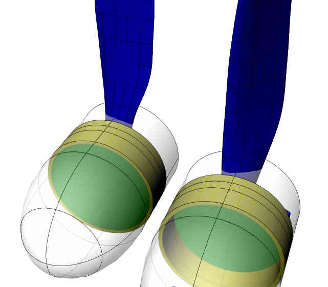
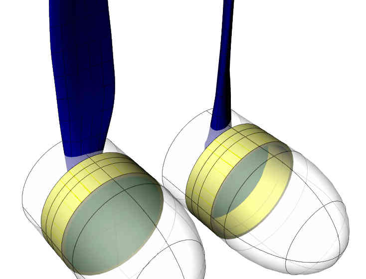
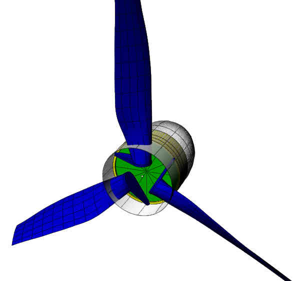
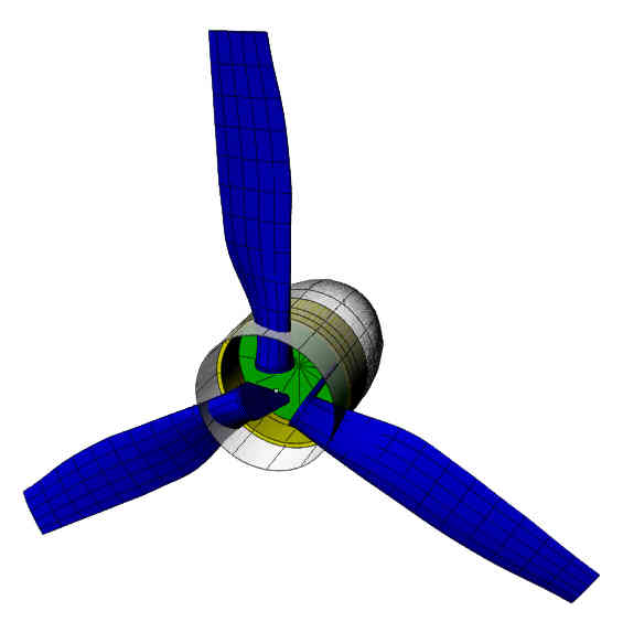
This is an old idea that I had a while back but
it took me awhile to refine the idea.
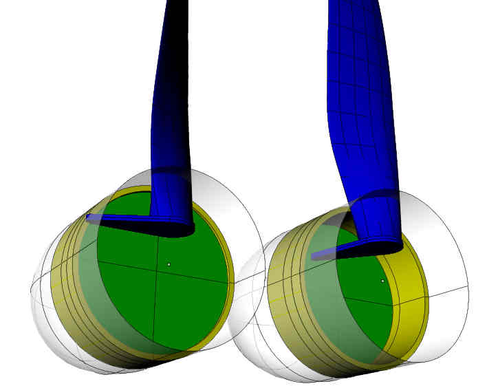
There is but one moving part other than the blades
themselves. There is a 14 inch diameter air cylinder piston
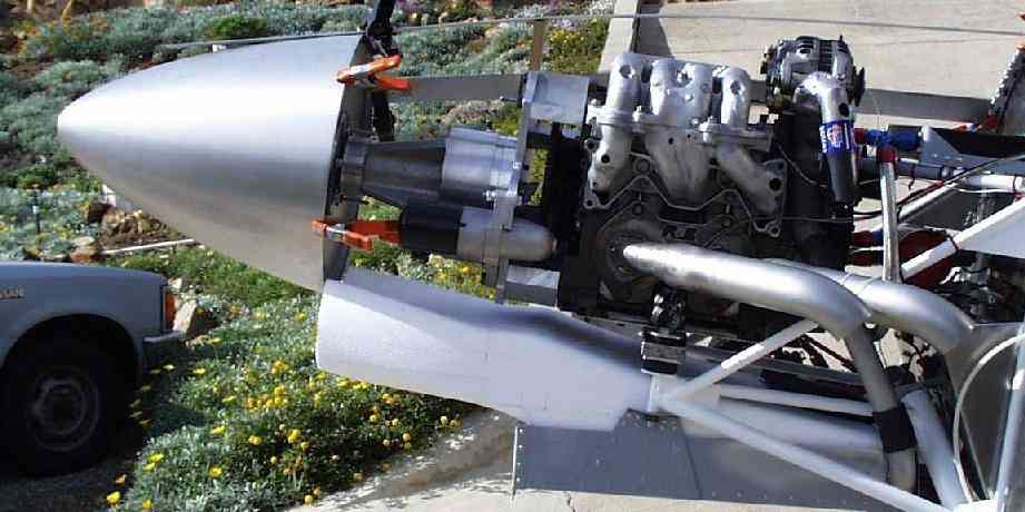
and cylinder built into a 14 inch diameter spinner. Fourteen
inch diameter spinners are a good idea for rotary powered
aircraft as they give more room under the cowl for engine
and cooling systems. More specifically they give more
room over the engine for the intake manifold.
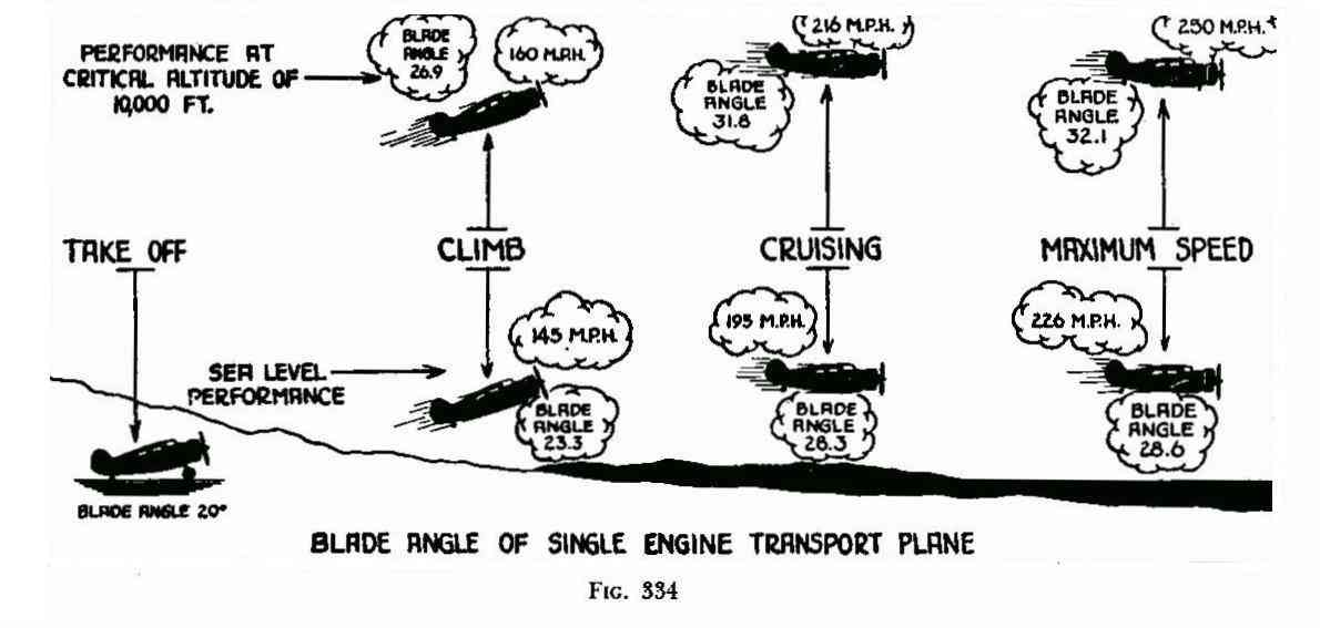
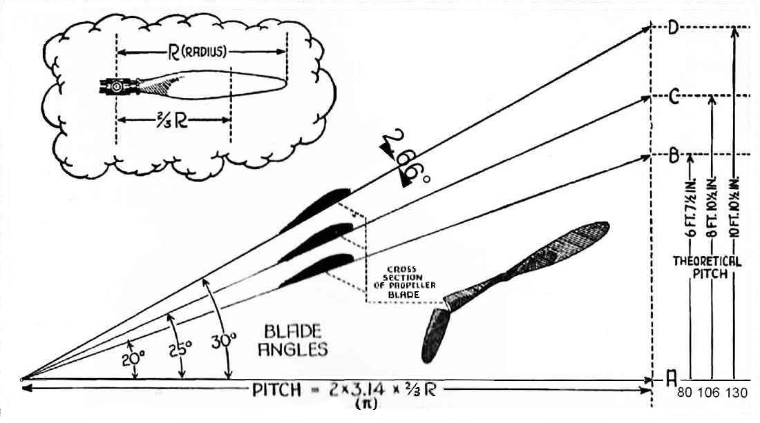
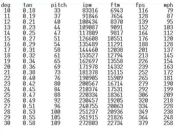
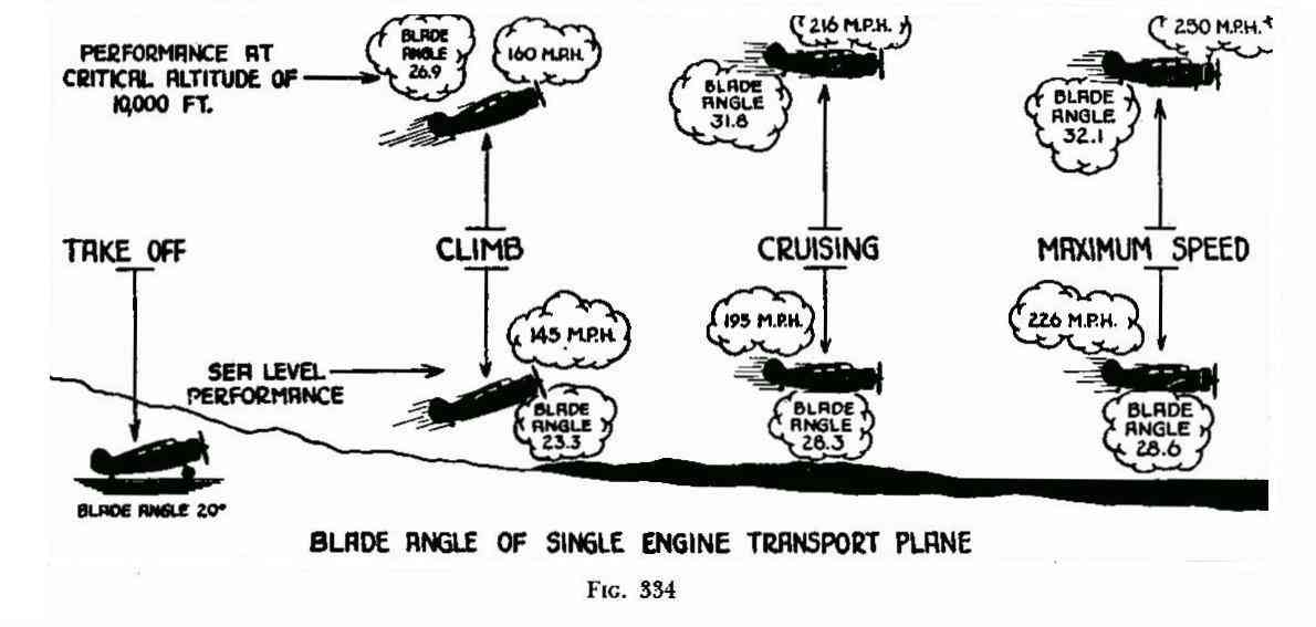
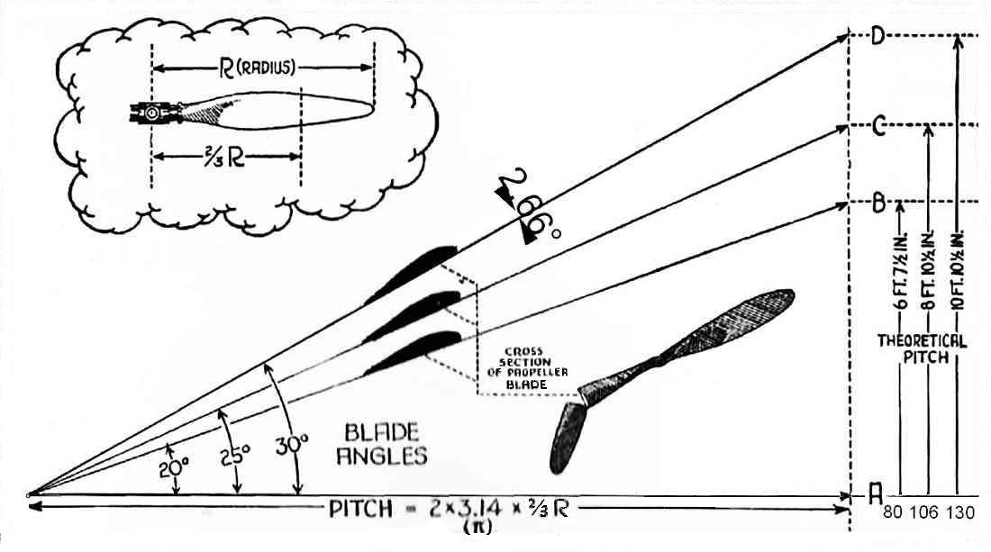
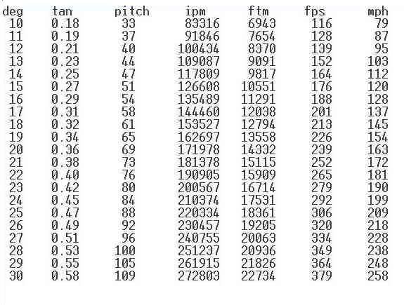
The stroke of the piston is 4 inches because that
gives a 20 degree change in pitch from climb out to
top speed. About what one needs.
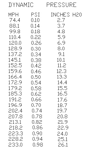
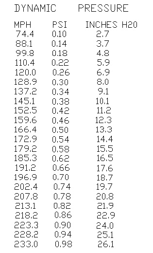
The piston is fed by dynamic air pressure entering a small hole
in the front of the spinner. At 100 MPH that is about 26 pounds
per square foot. At 200 MPH the dynamic pressure is about 100
pounds per square foot. A 14 inch diameter piston is about
1.1 square foot so the force on the piston is 27.8 pounds at
100 MPH and 106 pounds at 200 MPH. More than enough force
to increase the blade pitch with about a 7 inch lever arm.
Paul Lamar
Paul i think your blade action is on reverse,
cruise hight pitch and climb fine pitch
Jean Prudhomme
Congratulation Jean. you found the secret error. I throw those
things in from time to time to find out if anybody actually looks
at these messages :)
Paul Lamar
14 inch spinners are good, but 16 inch spinners are better- Like
the one from a Midget Mustang. The first 8 inches of a prop
don't do anything other than hold the rest of the prop on the hub.
Brian Trubee
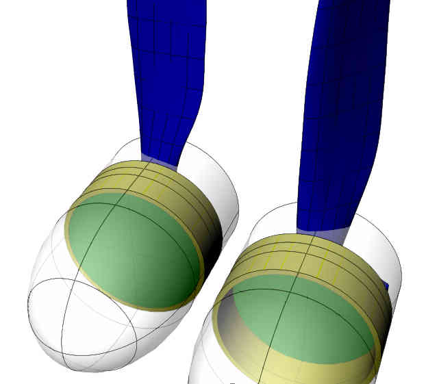
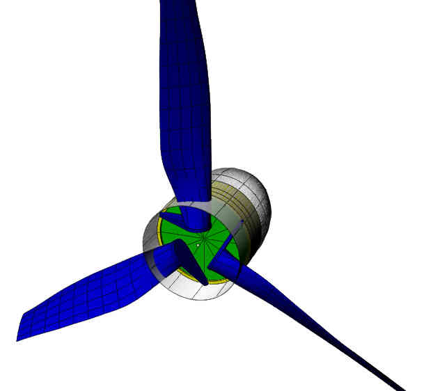
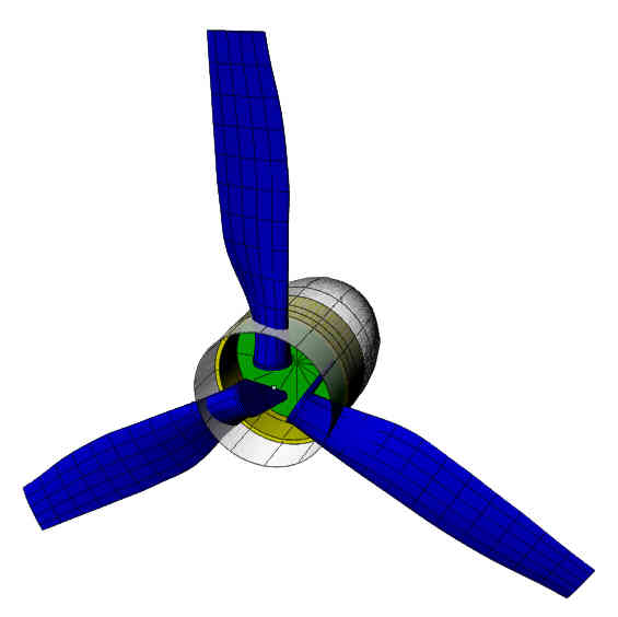
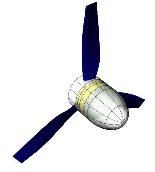
Here is the corrected design and 3 blade version are possible.
This is a 14 inch version but an 18 inch version would work
much better. The piston area is almost twice as much at 1.77
square feet. Force at 200 MPH than would be 177 pounds way
more than enough to change the pitch.
Paul Lamar
Interesting, elegant, entirely self-contained. A few observations:
- As rotational speed increases, the acceleration ("centrifugal force")
will
tend to force the control arms on the prop blades farther to the outside,
decreasing the blade pitch. Not a showstopper, just something to be
designed
around (perhaps with counterweights)
- Failsafe: Users would want some means to assure all blades could be
returned
to some satisfactory (and equal!) setting if something in the piston
mechanism
failed. (??A strong spring that pushes all the blades against the
"minimum
pitch" stops, released by a solenoid catch/melted nichrome wire after a
triggering signal from the cockpit?? Power supply?)
- Higher density altitude at same airspeed= less dynamic pressure and
lower prop
pitch, when what we'd want is greater prop pitch (right?). So, the
design would
have to be optimized for a particualr density altitude and conditions
outside
this would be somewhat non-optimum. Just a compromise, like so much of
engineering.
- As everyone realizes, the devil is in the implementation--bearings,
seals,
vibration tolerance, flutter control, etc
Mark W.
I figure we would set it up for cruise at 12,000 feet.
Another trick is to dive the airplane briefly and force the
pitch to increase then slowly level out. Pitch is proportional
to speed squared.
This technique is kind of an urban flying legion but in this case
it could work.
I also think the piston and cylinder are best done in carbon
fiber composites. A small diameter center cylinder can guide
the large piston.
The pivot axis of the blade is best done at the 1/4 cord point
to minimize the torque required to change pitch. If the pivot
axis is ahead of the 1/4 cord point the pitch will tend
to flatten automatically. If the pivot axis is behind the 1/4 cord
point the pitch will tend
to increase counter acting the acceleration tendency to force the
control arms on the prop blades farther to the outside, decreasing
the blade pitch. Small adjustable trim tabs on the trailing
edge of the blades can be used for fine tuning.
Paul Lamar
If the mechanism were designed so that the piston pulled (rather than
pushed)
the blade control arms against spring pressure, then simply breaking the
"pull"
linkage would allow all blades to spring back to the "safe" climb-prop
pitch
setting (though I don't know how quickly we'd overspeed the engine, PSRU,
or
prop if this happened). Setting up for a "pull" configuration might mean
putting
the prop blade and control mechanism in front of the piston.
Mark Waldron
I think that the rotary engine is ideally suited to be robust enough to
shrug
off overspeed conditions.
C. Smith
Even at zero pitch the engine is not going much further than 7500
RPM. The prop tips hit a supersonic brick wall. This is not a delicate
piston engine that self destructs at 100 RPM over the red line.
Paul Lamar
Yes, pro(p!)bably the overspeed situation might be self-limiting and not
an issue.
- Pulling the control arms (rather than pushing them) from a single
central location has four advantages:
-- As mentioned: In case the prop misbehaves, a pilot-initiated
severance of that one linkage and all the blades would go back to the
"safe" low-pitch setting automatically
-- All the blades are certain to move the same distance, even if the
piston binds up on one side and gets pushed out of a perpendicular
orientation to the cylinder walls
-- By simply adjusting the pull linkage length we'd get the ability to
adjust when the blades began to move in response to the piston travel, and
how far the blades go (max)
-- Lower friction. As shown in the (very helpful) drawings, the control
arm lobes would rub on the piston (friction could be miniimzed with
bearings/wheels, but that's "more stuff". If instead the piston pushed a
central rod that then pulled the control arms through a linkage, then very
little rubbing would take place during movement (except for the movement
of the rod within a rod sleeve, which is easy to lube and keep grit-free.
Anyway, all this is just "gilding the lily" of a cool idea.
Mark W.
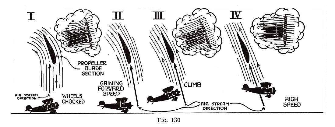
Would there be an issue for the piston when you pull up into a climb and
the
down going blade goes to a higher angle of attack ? This is when you want
the piston to move but there would asymmetrical pressures on the blades.
John
Not a problem if the piston is adequately guided.
Paul Lamar
This is an interesting idea. What's the total drag load (in lbs) of a
fairly efficient airplane while in cruise? It seems like 177lbs might
be kind of a lot by comparison.
It also seems like having only a small hole on the front of the
spinner might make the system not work. Air would just go around the
spinner? External diffusion style. Where's Peter Garrison?? LOL
It's still not a constant speed prop though - not that it's a big
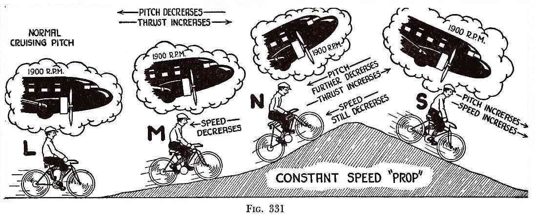
deal. This will hold a blade angle of attack that's approximately
proportional to
_indicated_ airspeed. It won't respond to power
setting. Advancing power will still increase RPM, and decreasing
power will reduce it. It's still better than a fixed pitch prop as
the engine shouldn't ever really bog down.
I'm thinking that a turbocharged engine might run the RPM above
optimum as altitude increases. The decreasing air density will exert
less pressure against the piston, causing (allowing) the prop to
flatten its pitch. But the engine power may remain constant, which
should allow the RPM to rise. Not a deal breaker by any means.. Just
thinking about operational behaviors.
Matt-
External diffusion requires the air next to the surface be at
or near dynamic pressure.
Most airplane's drag is rated in Equivalent Flat Plate Area.
That is defined by the overall drag factor C sub d times the frontal
area in square feet. It is in the range of one square foot to 10 square
feet. A Long EZ is about 2.5 square feet plus or minus .5.
Drag in pounds is then simply dynamic pressure in pounds per square
foot times the EFPA. Unfortunately that only works at low altitude
and near top speed.
When the speed drops below the best climb speed drag increase
due to the induced drag factor which is a function of span loading.
Ask me more about this later if you need more info.
http://tinyurl.com/38yk5kq
The tip of the spinner will see dynamic pressure.
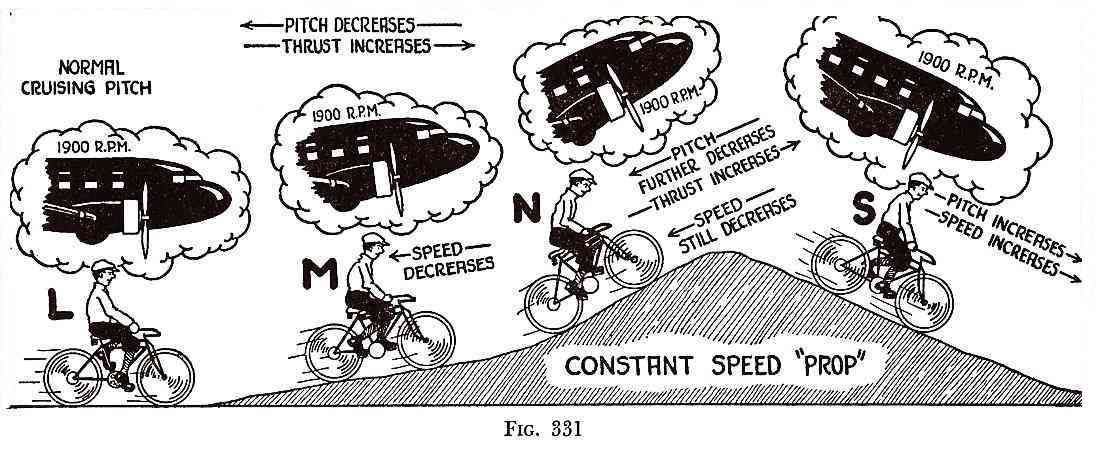
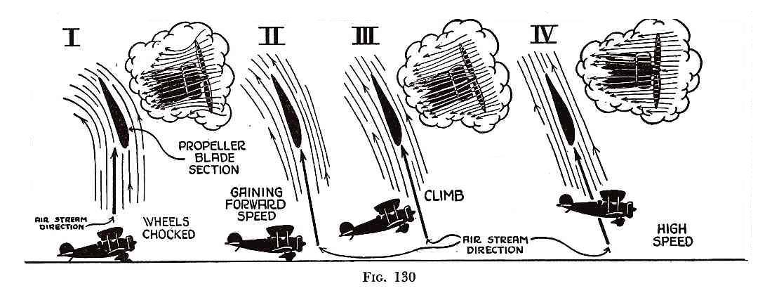
Pitch, in theory, will be proportional to the square of
the air speed in an ideal world assuming there is a linear
spring returning the blades to fine pitch.
Most lightly loaded experimental aircraft do not really need a CS prop
as the runways are relatively long and the power to weight ratio
is relatively high. Just choose the fixed pitch prop pitch
for max cruise speed assuming there will be about 20% slip.
Paul Lamar
--
The Rotary Engine NewsLetter. Powered by Linux.
ACRE NL web site.
http://www.rotaryeng.net
Youtube key word PaulLamar2
Copyright 1998-2010 All world wide rights reserved.