Paul,
Thanks for your book it's an interesting read.
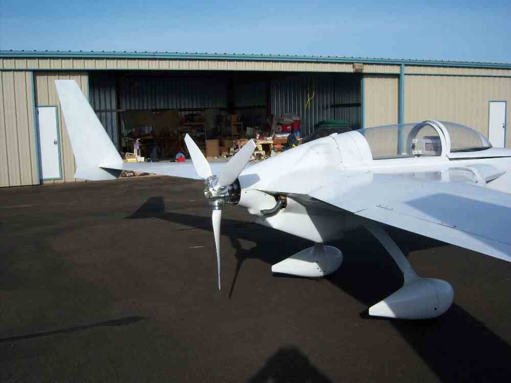
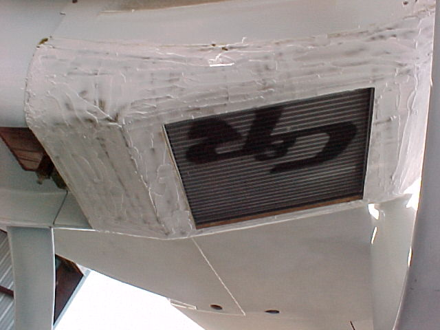
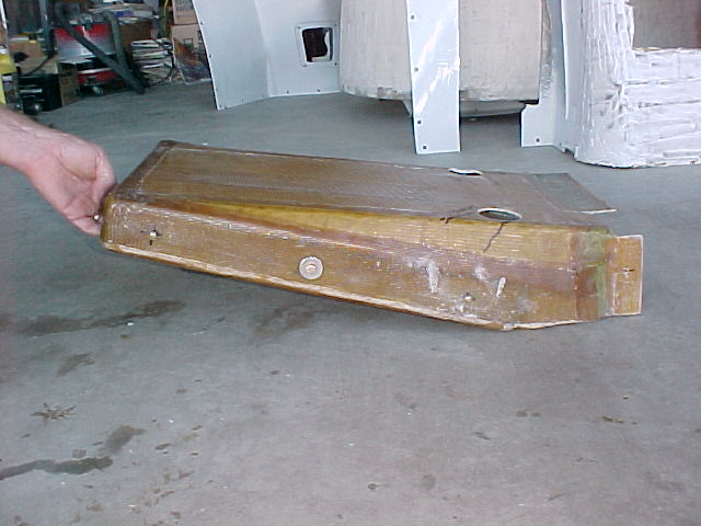
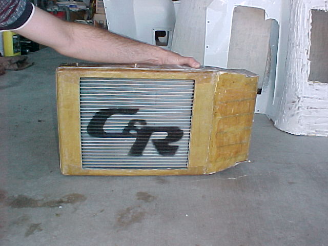
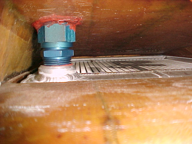
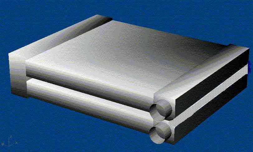
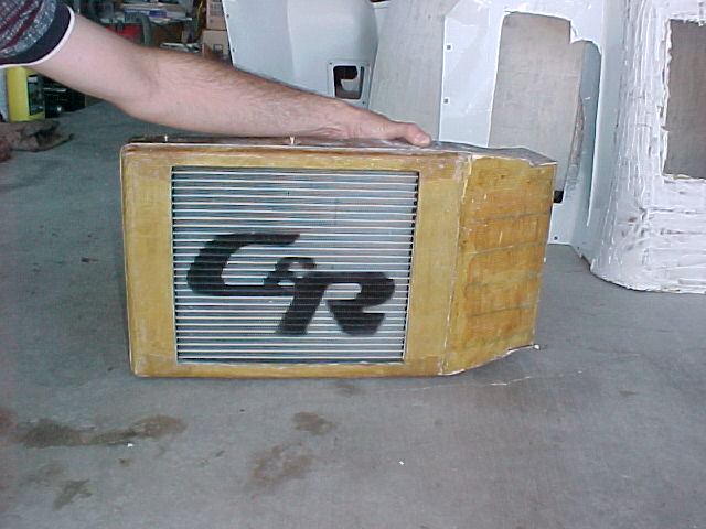
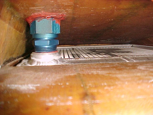
I have put together a quick layout of how I would like to do my belly
mounted radiator. The attached pictures I hope explain what I am trying to
accomplish.
You mention a separation of about 2" from the belly for boundary layer
separation, does this have to extent the entire length of the radiator or is
the way I show it ok?
I didn't see anything that gave me a frontal opening size relationship to
the area of the radiator, is there a percentage rule of thumb for this?
Any other suggestions on what I'm showing to improve would be appreciated.
Randy
Excellent illustrations Randy. Reduces the frontal area over the
splitter plate idea and is far more cosmetic. A Canard P51.
Is that Solid Works or Rhino 3D?
You will still need the Kays & London wedge inlet diffuser page 36.
Also you will need to take the bottom panel off as it will
retard the hot air flow out from the front back side of the
rad page 46. If you just lower the panel it will add frontal
area. Not good. Just do away with it and let the hot air
dump into that air stream.
I would use Venetian blind cowl flaps page 51.
I found the dims on the Neon rads I have. Here they are.
The rule of thumb is 20% of the frontal area of the rad.
With the P51 style scoop you are committed :) I dislike
commitments all my old girlfriends used to tell me :)
Paul Lamar
Randy,
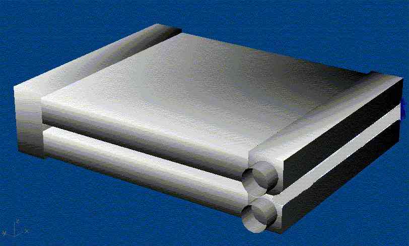
I see you have shown two radiators. Are you going to use
both of them somehow?
Doug in Japan.
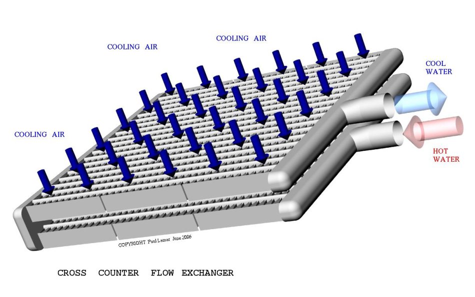
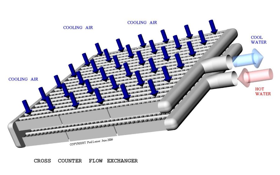
Yes. I was going to build a cross counter flow rad (book page 25 )
for testing but that is now far down on the priority list as Perry Mick
has already tested it and it works well. If you are pressed for
space it is worth it.
Paul Lamar
--
The Rotary Engine NewsLetter. Powered by Linux.
ACRE NL web site.
http://www.rotaryeng.net
Youtube key word PaulLamar2
Copyright 1998-2010 All world wide rights reserved.