Paul,
Thanks for your book it's an interesting read.
I have put together a quick layout of how I would like to do my belly
mounted radiator. The attached pictures I hope explain what I am trying to
accomplish.
You mention a separation of about 2" from the belly for boundary layer
separation, does this have to extent the entire length of the radiator or is
the way I show it ok?
I didn't see anything that gave me a frontal opening size relationship to
the area of the radiator, is there a percentage rule of thumb for this?
Any other suggestions on what I'm showing to improve would be appreciated.
Randy
Excellent illustrations Randy. Reduces the frontal area over the
splitter plate idea and is far more cosmetic. A Canard P51.
Is that Solid Works or Rhino 3D?
You will still need the Kays & London wedge inlet diffuser page 36.
Also you will need to take the bottom panel off as it will
retard the hot air flow out from the front back side of the
rad page 46. If you just lower the panel it will add frontal
area. Not good. Just do away with it and let the hot air
dump into that air stream.
I would use Venetian blind cowl flaps page 51.
I found the dims on the Neon rads I have. Here they are.
The rule of thumb is 20% of the frontal area of the rad.
With the P51 style scoop you are committed :) I dislike
commitments all my old girlfriends used to tell me :)
Paul Lamar
Randy,
I see you have shown two radiators. Are you going to use
both of them somehow?
Doug in Japan.
Yes. I was going to build a cross counter flow rad (book page 25 )
for testing but that is now far down on the priority list as Perry Mick
has already tested it and it works well. If you are pressed for
space it is worth it.
Paul Lamar
--
Paul
For years I was excited about that cross counter flow design you introduced and
actually did drawing to incorporate it under my engine. That is until I read a
comment last year on Stewart Component websites claiming the such setup increase
the back pressure and therefore flow significantly.
http://www.stewartcomponents.com/tech_tips/Tech_Tips_5.htm
I don't believe the longer effective water passages it will increase pressure 16
times but it will be significantly more than double. This got me thinking about
some to the water flow challenges I have had in my line of work. In essence,
when the water channels lengthen or restrictions are increased, the effect of
back pressure on flow will rise in a non linear fashion.
In a water heat exchanger, high velocity enhances turbulence, thus wall contact
time. Velocity is upper limited by restriction and internal pump fluid
slippage. Engine pumps are centrifugal devices hence produce highest flow
when the system has the least restriction. Said another way, maintain as high
as water flow as possible through the engine. To get 300hp out of the 13B
engine I'll need, according to Jim at Racing Beat, the man who's been there, at
least 40 gals a minute water flow. Choke the flow anywhere in the system and
pumping rate falls off as water pressure goes up. Knowingly increasing the
water pressure may not be a good thing for thin wall items tending to corrode
over time.
For comparison purposes oil heat exchangers have positive displacement pumps,
have to squirt a viscous liquid through inherently small openings and thus
have a slower flowing, robust heat exchanger in need of built-in turbulators and
must be able to withstand high pressures.. Many oil heat exchangers are
designed to be cross flow because the characteristics of wall contact time are
enhanced by the slower flow. Oil by nature as you know is less thermal
conductive than water.
This discussion basically boils down to whether it is more prudent to have a
single thick core thick radiator or two thinner ones in a reverse crossed mode
RCM like you have shown. Actually I have found that when the air gap between
the two radiators in the reverse cross flow is taken into account, the total
installed package is thicker than a single thicker unit.
Paul your thoughts that proper air flow through heat exchanger is paramount
and on that I wholeheartedly agree. I'm not so sure the old rule of the first
1/4 of the radiator does 50% of the cooling is correct anymore however. That
would depend on fin count air resistance, tube design, number of rows and how
well the unit is maintained. A clogged heat exchanger is as good as the dirt it
catches. Dave Garber showed me a very compact design unit he had made that
used two rows of the newer overside elongated tubes. These are about 1.5 in"
in length but essentially the same standard width. The Dave Garber design
installed package thickness came out to about 2.5 inches. compared to close to
4 inch thick for a similar RCM design. That is assuming a one inch air gap
between the heat exchanges helps isolate infrared heat transmission.
In Dave's design, air flow had to traverse about three inches to get through it
though. The tubes were angled as was the heat exchanger so air flow was
actually parallel to the fins and that might be a deciding factor in the high
performance he experienced. So high that he had to cover up the first few
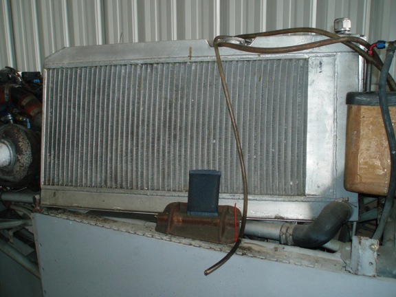
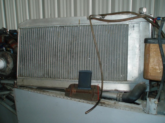
inches of it as you can see by the photo. His heat exchanger wetted area is
about 12 inches tall by 28 inches long. . Thats my 8cm x 11cm (3.1/8" x 4
3/8") wallet in the foreground for scale purposes.
I will try an identical system but lay it on its side under the engine and make
it 16" wide (max 20" with the side tanks included) by 19" or 20" in depth. I
'm not sure how to angle or curved the side tanks to help insure even flow
distribution though. Logic dictates at center inlet and outlets with the tanks
sides curving out toward the ends. Understanding how fluids flow is hard to
predict other than it takes the path of least resistance.
Doug in Japan
Well apparently Stewart did not read Kays & London's bible Compact Heat
Exchangers :)
==========================================================================
"The design of a heat exchanger involves a consideration of both the heat
transfer rates between the fluids and the mechanical pumping power expended to
overcome fluid friction and move the fluids through the heat exchanger. For a
heat exchanger operating with high-density fluids, the friction-power
expenditure is generally small relative to the heat transfer rate, with the
result that the friction-power expenditure is seldom of controlling influence."
[What they are saying here is the HP consumed by the water pump is of minor
importance. In fact the Mazda pump only consumes about 3 HP.]
"However, for low-density fluids, such as gases, it is very easy to expend as
much mechanical energy in overcoming friction power as is transferred as heat."
[What is being said here is HP is consumed by cooling drag. Since cooling drag
can be as high as 30% of over all drag the HP could be as much as 30% of 200 HP
or 60 HP. As you can see cooling drag becomes a very important issue.]
"And it should be remembered that in most thermal power systems mechanical
energy is worth 4 to 10 times as much as its equivalent in heat."
[Here they are referring to the heat balance of most internal combustion engines
that only derive about 25% to 10% of the heat energy in a gallon of fuel as
mechanical HP.]
==========================================================================
Builders have done some really dumb things like use electric water pumps
with 1/10 the HP and got away with it. The early Mazda pumps, many people
still use, have a restricter in them. Mazda woke up with the RX8 pump.
You need my book or Kays & London's book Doug :)
Paul Lamar
--
The Rotary Engine NewsLetter. Powered by Linux.
ACRE NL web site.
http://www.rotaryeng.net
Youtube key word PaulLamar2
Copyright 1998-2010 All world wide rights reserved.