Scroll down to see new messages.
Hi there, I live in Ca and I suppose you live around my neck of the
woods, I am up in Sonora, closest airport is Columbia.
I read your article on the Fuel Injection installation on your rotary
engine website with big interest.
I have a VariEze, that I just love, it is very efficient.
I understand that Klaus S, have a similiar system for sale.
I want however a sequential Fuel injection system, and he claims that
his system is not sequential.
I don't know about rotarys, but in piston engines (I have an O-200), the
efficiancy will go up if you use a sequential FI system.
Soooo...looking at your plans on how to build one, I looked and looked
and finally I decided that the system you are proposing is a very good
system, and it can be made sequential.
The key question here is basically, the function of the 555 chip.
In order for this to work, the 555 chip has to open and close ONES per
command (Per trigger) .
I looked at the system, and can conclude that all the indication systems
can be common, intake pressure probe, etc.
The only difference actually is that there has to be four triggers,
instead of one. One for each cylinder, (I know, some more sophisticated
systems just have one camshaft sensor, but that means I have to ad a
timer clock, and it will start to be complicated in that way, I want to
keep it as simple as possible, and have four trigger points is not that
hard.
The whole question that will make or fail this project is the way the
TLC 555 chip works.
Can you please tell me how it behave once it is triggered, will it start
pulsing, for a while, (on and off) according to the internal clock, and
stop after a while...or will the TLC 555 shoot ONCE, after each time it
is triggered?
Reason I am asking is that a batch fired system , doesnt really matter
that much, the injector can sit and pulse, , and shoot fuel per the
pulses it recieves, no matter if the intake valve is open or not.
That, ( in a piston engine....and I assume also in a Rotary engine) will
lower the efficiency of the engine, as fuel will be delivered
differently for each stroke.
Some intake strokes, will get a little bit, and when the valve closes,
the injector squirts a bit more, and when the valve opens next time, it
squirts again, and now the engine is sucking in the previous fuel, plus
the fuel it is currently delivering.
So, some strokes will run lean, some is just right, and some is rich.
Therefore, if I want to build a FI system I want to build the most
efficient I can do ( Direct fuel injection will be a bit too much
problem to handle though, so on that I will pass) , and the best I can
build would be a sequential FI system.
We will run into another problem here, I will need bigger injectors, as
a batch fired system have no time restriction on its fuel delivery, ,
but a sequential system has to deliver all the needed fuel in a quarter
of the time. ( Intake stroke, or the time when the intake valve is
open.....it actually has a little bit shorter time to accomplish this
in, as you can not start spraying in fuel, just as the intake valve
opens, you have still pressure in the cylinder, and the full effect of
the overlap has not starting to take effect just yet.)
So I have about one fifth of the time to deliver allo the fuel I need.
Now, as I understand, the size of the injectors doesnt really matter,
this system can handle it all pretty good, and actually run the
injectors straight.
You seem to have already been doing this a little bit, and maybe can
come up with some general advice on this, but my main question is if the
TLC 555 chip will trigger once and give one pulse, or if it will
continue to pulse, after each time it is triggered?
Also, I live up in the boondocks, and the only thing around here is
Radio Shack, and they don't have much, are there a good electronic
retailer around where I can stock up on all the things needed around
here, ( lets say Stockton, Manteca, Modesto or thereabout)
I saw from the photos on the website, that you have some goodies, and
have made a really good set up, circuit boards, good fitting heat sinks,
and everything, did you do them yourself, or do you have a bunch
produced, ( for sale) .
I would appreciate to hear from you, and kick some ideas with you.
Roger Isaksson
http://www.rotaryeng.net/simple-cheap-555.html
I am not sure our approach will work as we have not tested it yet.
At 7500 RPM one only has about 8 milliseconds to work with for one
RPM. We are about to test it in the next six months unless something
more important comes up. I am am not sure how Klaus is doing it.
DigiKey or Mouser both give fast service on mail orders.
http://search.digikey.com <http://search.digikey.com/>
<http://search.digikey.com/>
We also don't have any parts for sale just yet but you are welcome
to use our art work to build your own PC boards.
Frankly I am not sure timed is the way to go. I am about to instrument
and test another EFI system already sold for use in rotary aircraft
engines and will know more about that shortly.
http://www.hytekautomation.ca/
We will record when the fuel is injected into the manifold relative
to the e-shaft angle and of course how long the injector is open.
Manifold pressure will be recorded in several different places
to check for aerodynamic differences. All of this will be done over
a range of RPM's using an actual propeller for a load at a rate of
1000 measurements per second.
Stay tuned.
Paul Lamar
Hi there Roger here again,
Have been studying up a bit better on the rotary engine, whoops, didn't
work the way I thought, oh well.... I told you I was a bit weak on it.
Well I am in this for the FI and the ignition systems, they look great.
Fourstrokes are my forte, but hey I am eager to learn.
Ok back to the FI and so on....the FI system I got fired up about, do I
understand it right that no one have tested it, the one with a 555 chip???
Hm...also, I saw another cheapy made and great looking, very simple
ignition system, and wonder, ...do you think that the diodes can light up
the FI system as well as the magnetic trigger can?
Been thinking of what bugs most people, when it comes to engines, that
is ...to be able to start them up.
So I'm thinking, like in a fourstroke, or perhaps also in the start up
sequence of a rotary, lets say that under 100 RPM the system would go
over to a start mode, meaning, in the case of a four stroker, ( or
perhaps also a Rotary, realize now that I don't know half as much about
those than I thought, so I better hold my horses when it comes to
those)...so ok, lets talk fourstroke.
If in the starting moment, the ignition system would fire every minute
from 12 o clock to 4 o clock, giving the ignition system plenty of
chances to arrange a meeting between one oxygen atom ( comes in pairs)
and a fuel molecule, to have a happy marriage.
Lets say that in the cockpit there would be a three way switch, off ,
start and run.
Most probably there would be a second, set of ignition system, most
probably a set of Slick or Bendix magnetos sitting there, but they would
in the firing sequence fire with the clicker, and that is pretty much on
the 12 o clock position, so the magneto could be left alone, and on ON.
The electronic ignition would be set to START.
Ok there would be a disc, with holes set on two race tracks, and each
race track would have it's own LED, and sensor, the switch in the
cockpit would shift between the two LED's and trigger sensor.
The first start position, would have a disc with a lot of holes in it,
that would make the trigger fire from 12 o clock to 4 o clock several
times, and now you hand prop the engine, and make the spark plugs fire in
the start mode.
While the engine is hand propped, the ignition will be served from both
the magneto independently, and from the electronic ignition that would
trigger the spark plug very often,from 12 o clock until it reaches the 4
o clock position.
Once the engine starts, the magneto will automatically start firing in
advance, and the electronic ignition would not do anything else than
just firing away into an already burning combustion, until the pilot
have walked back to the cockpit and switched the electronic ignition
from START to RUN, where the electronic ignition now will fire in unison
with the magneto.
One more thing and this will be as good as it will get, able to advance
the ignition. By a simple mechanical device run by a perhaps small
stepper motor, the C clip arrangement of the Diode and trigger, can be
rotated around the periphery of the rotating timing wheel, and the
setting controlled by the pilot.
I have some questions.
- The circuit board I can see in the pictures for the 555 system, did
you do them yourself, or did you order them somewhere...just wonder how
I can get my hands on some of them.
- What pressure sensor are you using for the FI system, it didn't became
fully clear of the description of those, there was a lot of serial
numbers on chips, and other electronic components, so maybe I missed it,
but I am thinking that maybe it wasn't there... could not find it.
- The adjustable resistor, that will adjust the timing of the FI systems
firing period and are suppose to sit in the cockpit, is a bit unclear to
me. Resistance is measured over two points, but the resistor described
had three legs, and I wonder how the internals of that variable resistor
is wired?
Preciate it, and Happy New Year
Roger Isaksson
Your starting scheme can be made to work as the photo interrupter
circuit has a lot flexibility.
We use about 50 psi so it uses a stock automotive EFI pump and
regulator.
I get my circuit boards from
http://www.expresspcb.com/
They have free PC board design software. If you download
it I can send you the files I have so far and you can buy
boards from them. Or you can use them as a starting point and
change them to suite yourself. Here are a couple of jpg of boards
that I have done. The software is easy to learn.
The pressure sensor is a $10 Freescale part from Digikey.
The mpx 4250 data sheet is attached.
The leaning pot on the dash board is an off the shelf variable
resister. Try 10K for a wide range of mixtures. It does not change
the timing but only the pulse width. Narrow for lean wide for rich.
I modified the ske to show how it works.
Also an ABS sensor from Pep Boys is cheaper than the Mazda crank
angle sensor. It works the same.
If you are using this on a piston engine you will have to sense
the cam shaft position as it rotates half as fast as the crankshaft.
a timed one rotor squirts every rotation while a timed one cylinder piston
engine squirts every other rotation so you need to know when
the piston engine is on the intake stroke. Probably the best
place to do that is on the mag drive gear. Probably one reason
Klause does not use a timed injection :) This 555 system does
not need to be timed. You could let it squirt on either the intake
stroke or the combustion stroke as the intake valve is closed.
Another way of doing it is a capacitive spring loaded clamp on an
ignition wire to sens when the engine is on the combustion stroke.
You will be on the bleeding edge when you do that as I have
never used that trick :)
Paul Lamar
-- Paul,
Did study the explanation on the leaning system,, clear as a
crystal ball, ok got it...thanks.
Are gathering all the info for ordering all the needed stuff.
Now the billion Dollar question...
Here is this pilot sitting in his cockpit and are adjusting the flow to
the engine...ok good enough,.... but how would he know when he is in
stochastic range, lean or fat?
There is simpler systems for cars, where you can just install an extra
oxygen sensor, and there is a fuel/air mix gauge you can read off, but
as most aviation based fuel, have quite a bit of lead in it, and with
leaded fuel, the oxygen sensor will not be long lived, and will start
showing erroneous values pretty quick.
If it would not be for that darn lead, the oxygen sensor is probably one
of the most gallant and excellent solutions, the oxygen sensor, is not a
switch but a galvanic element, and have very fast reaction time, and it
reads very precise.
And it is so darn simple that it is almost ridiculous, an oxygen sensor,
a needle gauge up front, and a circuit going through it, that's
all....hmmm....
Damn lead.
Wonder if there is a way around it????
I am aware of all these "big" solutions that can read air /fuel ratios,
with throttle position sensor, mass airflow meter, computer programmed,
and the whole jadijada, but not the simple elegant solution.
If the pilot can not set his fuel mix to the value he wants, he just
wouldn't know where he is on the fuel map, he can sit and turn that
adjustment knob as much as he wishes, but he will never know what he
will be feeding the engine. All he would know is turning to the left
would mean leaner, and to the right would mean richer, but he wouldn't
know, other than getting indications from indirect measurements, like
cyl head temp, exhaust temp, or listening for rough running etc.
Compared with a carburetor, a FI system is a precision instrument, but
he would be like a guy sitting with a precision sniper rifle, with a
high magnification scope, and shooting........ blindfolded........ all
he can do is to aim in the general direction, and cause a bang.
Any thoughts in that direction?
Roger Isaksson
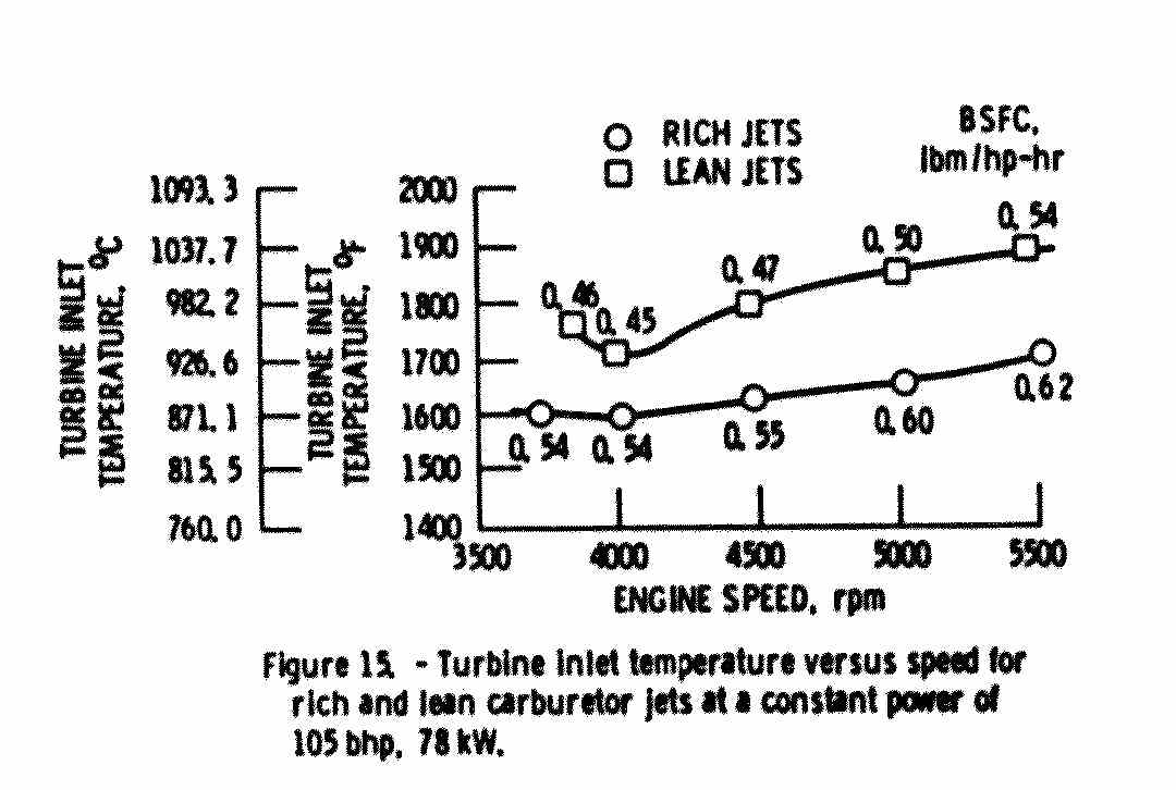
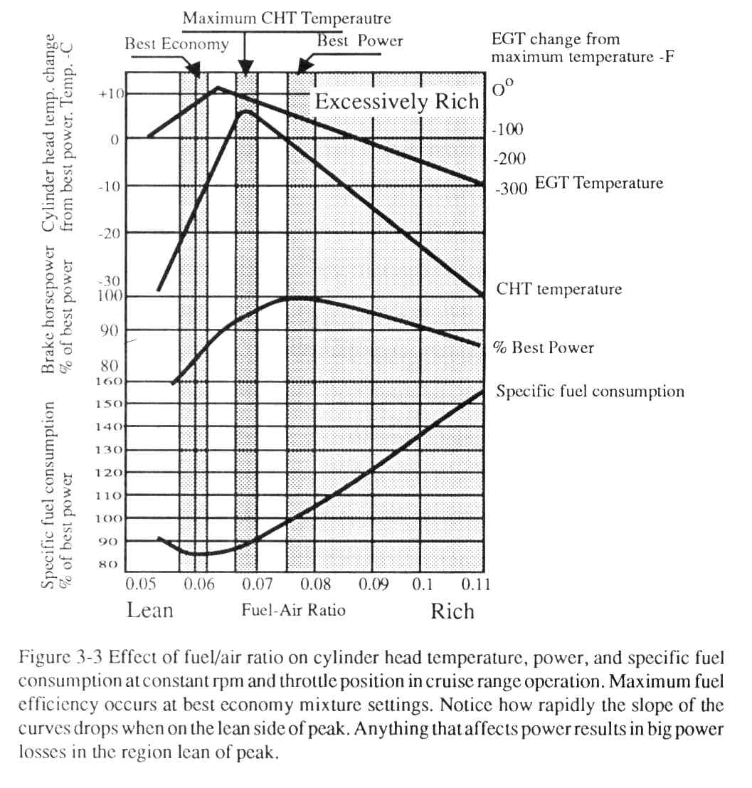
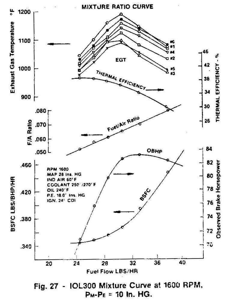
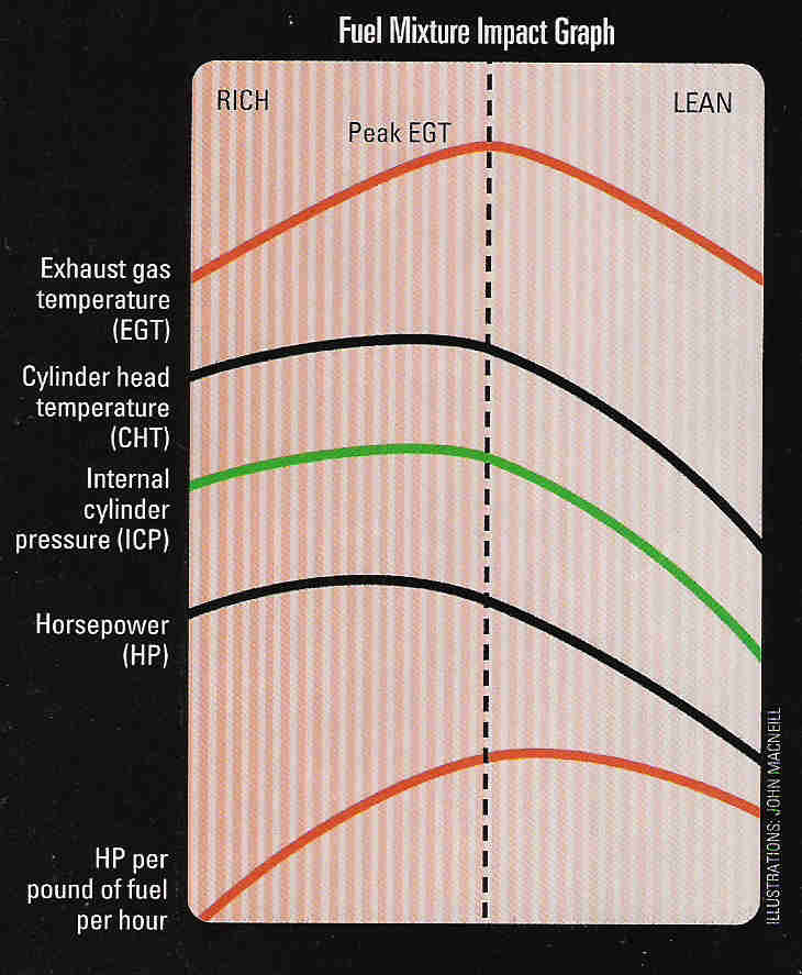
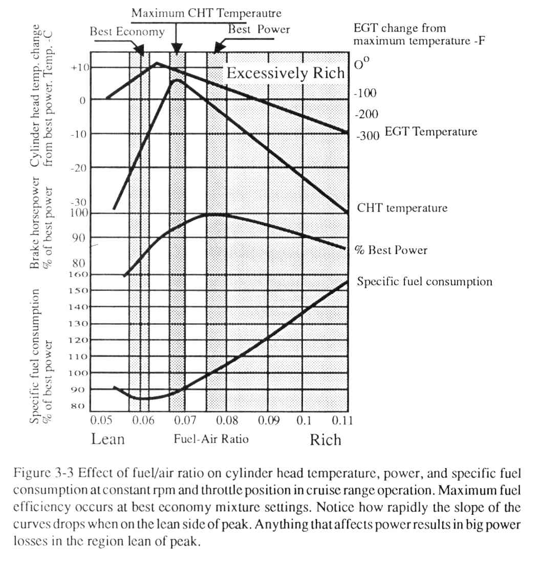
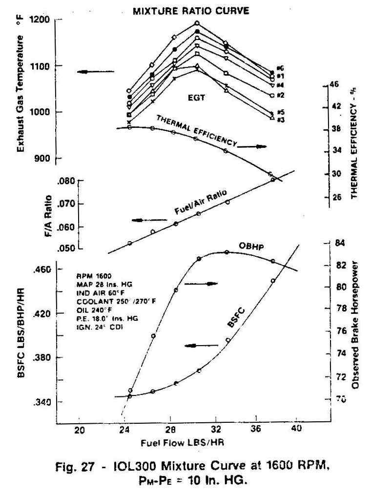
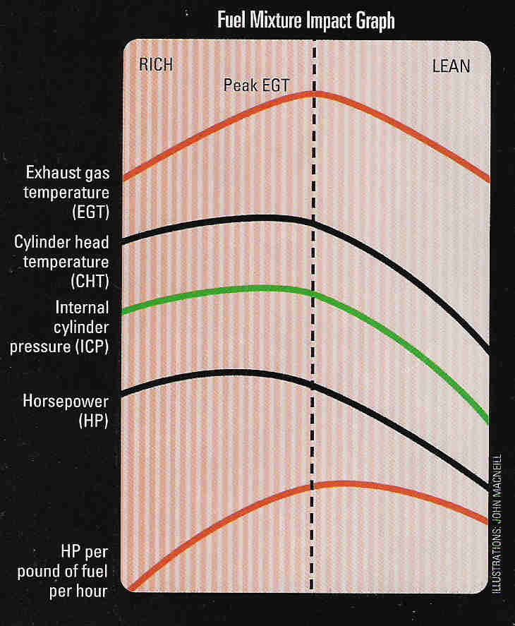
Pilots are trained to adjust the mixture according to Exhaust Gas Temperature.
When you start the engine it is rich and the EGT is cool.
You take off full rich at full power. When you reach cruising altitude
and want to minimize fuel burn you lean the engine and watch the EGT rise. You
keep leaning and the EGT reaches a peak (stochastic) and starts going down. When
it reachs about 50 degree F lean of peak the fuel burn or BSFC is the lowest.
The Holy Grail of EFI systems is to do this automatically. It is
called auto lean. It was available on turbo compound CW R3350
air liner recips back in the 1950's. Mistral also offered it
on the rotary before they went bankrupt.
Unfortunately Tracy's system does not do this and that is one reason
it is so hard to tune. Tracy makes a big deal out of tuning the engine
in the air without a lap top computer in the cockpit but then he also uses
a crude and cheap manifold pressure sensor as the main indicator of
the power required. The system cost over $1000 dollars so IMHO he could
damn well include a mass air flow sensor since they are universally
included in every car EFI on the planet. The manifold pressure sensor
sampled by a computer is a one millisecond snap shot of what is going one
in the turbulent intake manifold at that particular time and that specific
place in the manifold.
So far every installation is different as every side port manifold is
home made. Consequently the mixture map is all over the playing field.
In the 555 system the pressure sensor does not give us a snapshot
but automatically averages the manifold pressure readings. A simple
capacitor can and will improve the average in the 555 system.
Paul Lamar
The Rotary Engine NewsLetter. Powered by Linux.
ACRE NL web site.
http://www.rotaryeng.net
Youtube key word PaulLamar2
Copyright 1998-2010 All world wide rights reserved.