Dale ,
I am starting to lean towards doing the 555 system, it's a personal
challenge...I can see from the correspondence that you all have, that in
many respects, you are well over my head, and I want to struggle through
something like this, I really don't mind it, but don't want a big
research project either, so I think a 555 system will put me about where
I need to be. ....but by all means, I wouldn't mind looking at the Ford
system as well, George mentioned it earlier, and I promised to follow up
on it, where can I get info about the Ford FI system?
Roger Isaksson
In my computer experience basing anything on a sole source device
is sooner or later going to bite you. Manufacturers move on.
They MUST continue to lower the cost by redesign or go out of
biz. The 555 is made by half a dozen companies world wide.
It so ubiquitous you probably have two or three in the house
with out knowing it :) Look inside the toaster as a start :)
Paul Lamar
Paul,
Oh man you're right, ....I just looked in my toaster, and lo and behold,
there was a complete sequential FI system, I'll be darn...how did
you.....??.....
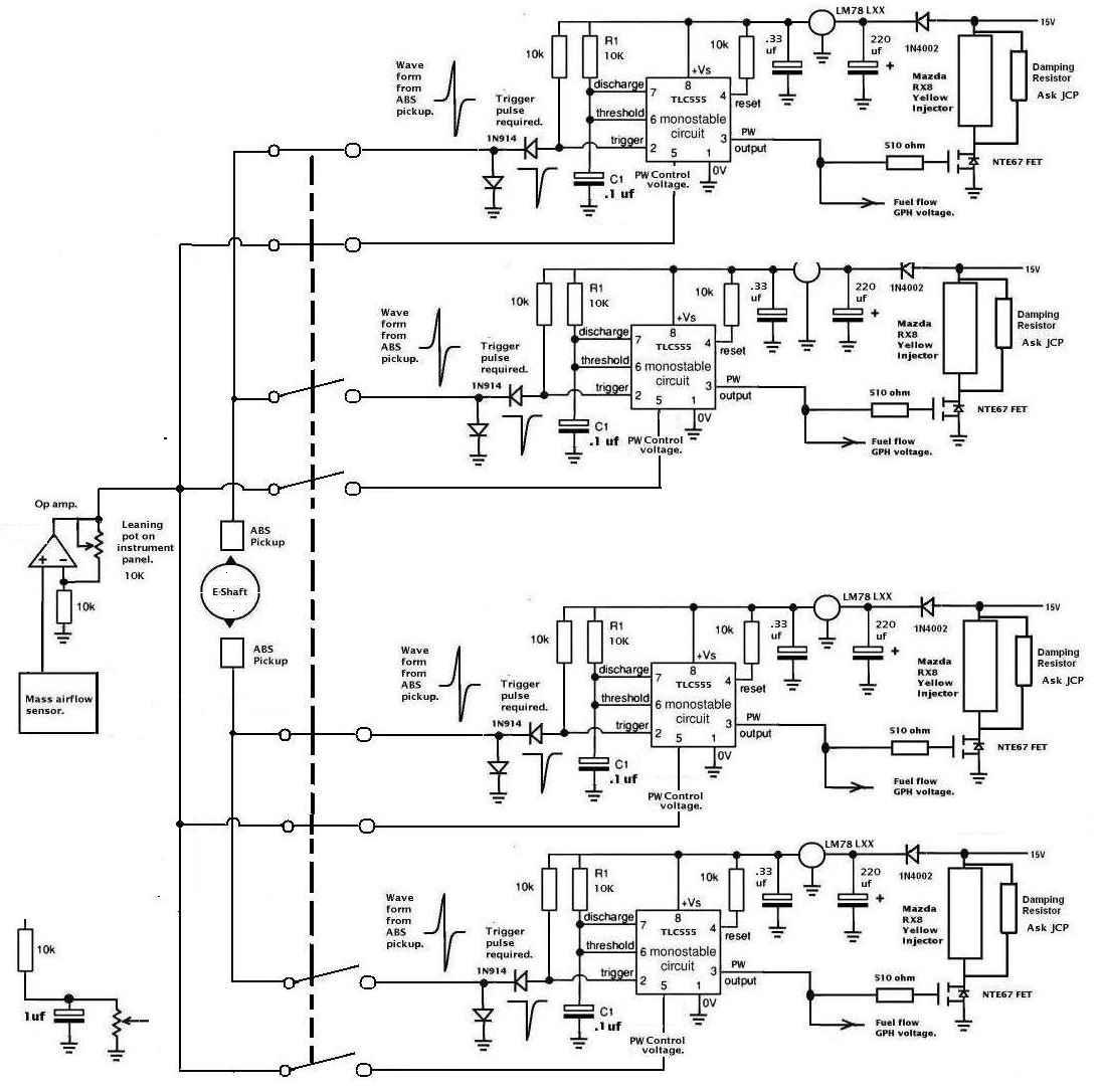
Paul I am about to order some parts, and could use some explanations on
a few things, studying the drawing on the 555 system, to start up with ,
the
resistor in the schematics between the 555 chips nbr 7 and nbr 8 leg,
have no value, any value for it?
C1, looks like a capacitor to me...any value for it????
On the trigger control schematics, there seems to be a capacitor that
has a value of 0.05, but it doesn't say if it is Farad or Microfarad, I
guess it is Micro.... right?
Looking at the scematics of the fuel adjustment, the variable
adjustment, I got one on about 10K Ohm right now, as per
recommendation, but wonder how much of an "Ohm window" it has to cover.
Adjustable resistors, ( we're still on the fuel adjustment) comes in
different forms, scewing, taper or as you described in your diagram,
with a reostat in it. Those seems to be the most frequent ones I
encounter.Does it matter what type it is or are there a bias towards a
special type?...as long as they can handle the voltage and give stable
Ohms they are set to ...right?
Also, as my first trial I will go for the pressure sensor, but looking
at the site over pressure sensors, I get lost prety quick, I understand
they have to have a range between 1 atmopspheric pressure and zero.,
even with values like that, they come in a variety of classes, so I
could use some guidance as to exactly which one is the one, please.
Talked with a FI guy recently, he claims that an oxygen sensor can last
up to 50 hours with leaded gas, after that they will still work, but be
somewhat slow. He's been racing, using leaded race fuel and methanol,
and at least with that mix, he give them about 50 hours.
For best stochaisitcs, he is saying that the easiest way, if an oxygen
sensor can not be used, is just to watch the EGT, well...we seems to
come back to that, I was hoping to have a display with a number, but, I
digress,..... I just watch the EGT....easy enough.
Have two conflicting data on the pressure sensor,I talked with this FI
guy, that claims the intake pressure will stay constant, and I have to
adjust, the same as a carbureator, as the pressure reading will stay the
same, as I go up in altitude.
Then I went over and had a call to an old friend, he's an old Mc Donald
Douglas retired flight engineer, he's of another opinion, ( He and Ken
Rand came up with the KR aircrafts in the 70's) and he thinks that a
pressure sensor in the intake manifold will pretty much align itself
with altitude, I asked him if he thought it would be completely linear,
he could not swear by that, he thought that was possible, but thought
that at least a basic adjustment would take place automatically.
Good enough,... so the pendulum of favourable sensors for the 555 system
, seems to swing over to the field of pressure sensors right now...I
will try with that set up first.
So Paul, we will se what works,...... your original choice of
sensor. ....according to my own bias, ...the FI guy, ....or the flight
engineer.....
*****whirling drums*****
Roger Isaksson
I am sorry. I think you are referring to R1. That is 10K.
The cap is micro farad.
These are starting points and may have to be adjusted
Later on.
Here is an earlier complete system using a mass airflow
sensor which now I don't think is the best way due
to non linearity. Note the modularity and redundancy.
Each injector has its own EFI system and power supply :)
The ABS sensor has a different and simpler signal conditioning
circuit.
Variable resistors come in different qualities, prices
and number of turns. Ten turns can fine tune the mixture
more precisely. The AN type are probably the most reliable.
Go on digikey.com and download Section g of the catalog.
Go to page 2020. You will have to experiment a bit to get
it right. Do that with cheap pots and then put in a good
one when it comes time to fly.
The pressure sensors are in Section N.
Paul
--
The Rotary Engine NewsLetter. Powered by Linux.
ACRE NL web site.
http://www.rotaryeng.net
Youtube key word PaulLamar2
Copyright 1998-2010 All world wide rights reserved.