Hi Ed,
My thoughts on making the rotor housing steel liner for a 13A/16X
size radius
would be to try to get a 13A engine. Doug, would you have any
leads on one in Japan? With that we would have the shape of the
inside. Casting a steel shape that is the inside dimension would
help form the proper shape. We would need a die for the outside
so it forms correctly. Figuring the inside circumference would
enable machining a 4130 pipe ID to that dimension. Then machine
the grooves in the OD with a tapered burr so the cast Al forms
into it and can not come "unglued" or separated. Then forming it
with the dies to the shape. The Al could then be cast around it
and the width machined. The area for the Pport could be left
without cooling to eliminate sealing there, and the port almost
ready to go.
Anybody alse have an idea on this. Paul, what is the thickness of
the Mazda
steel liner?
Dale Davies
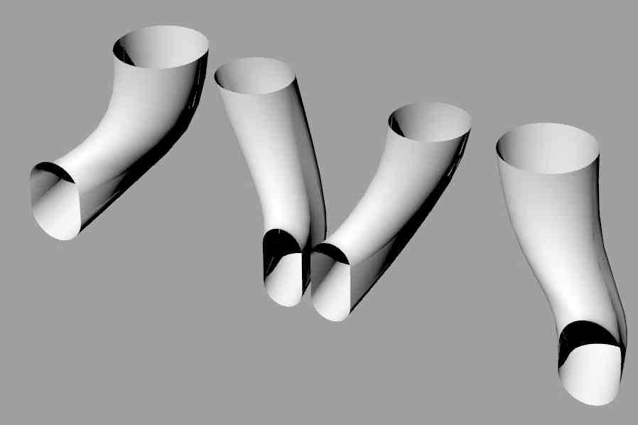
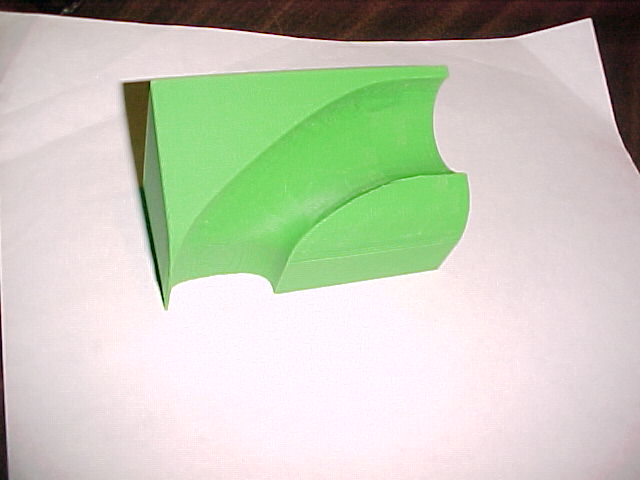
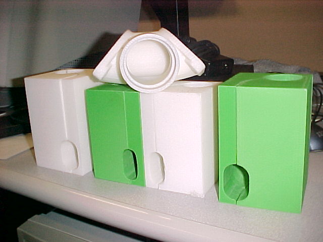
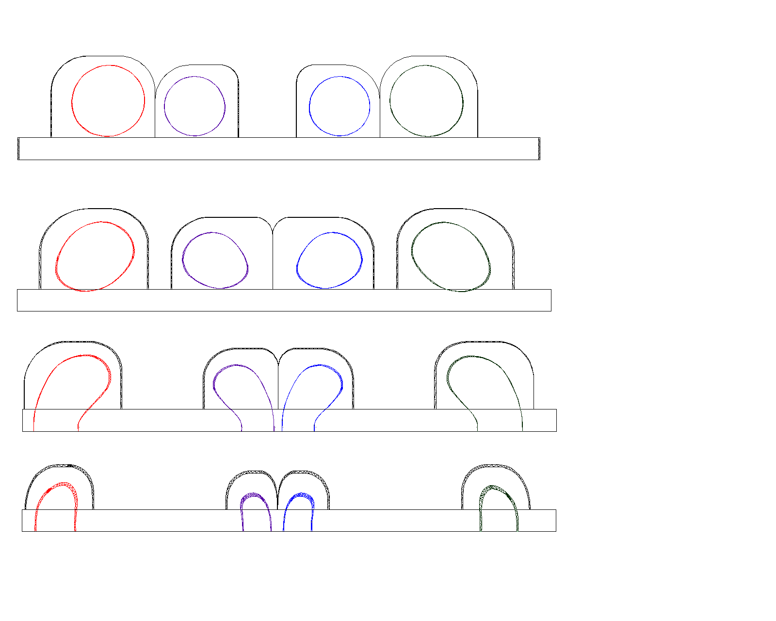
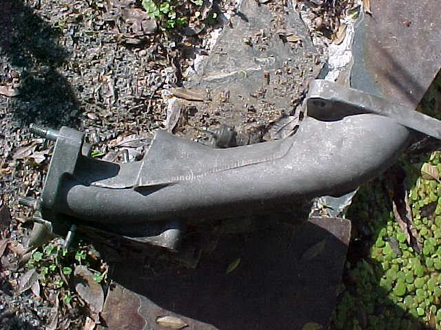
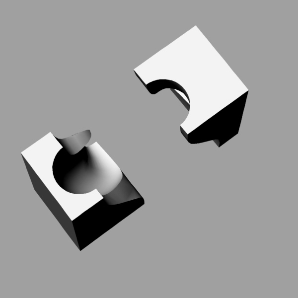
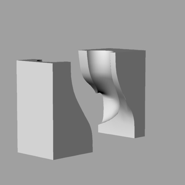
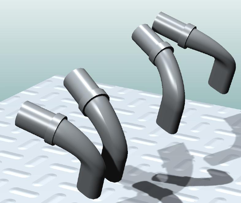
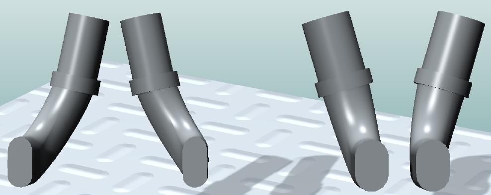
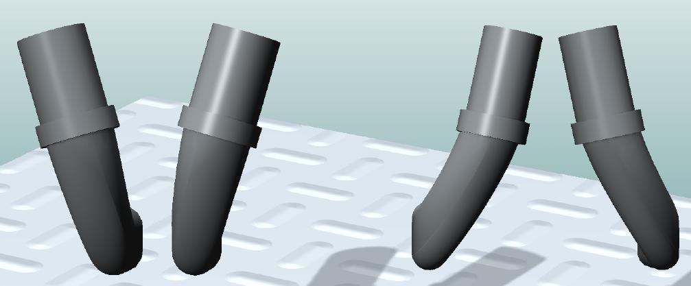
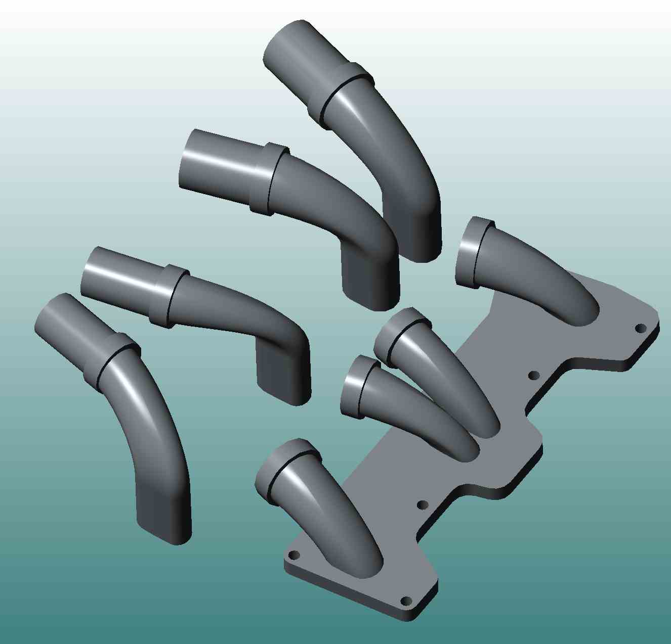
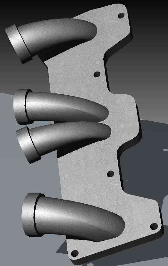
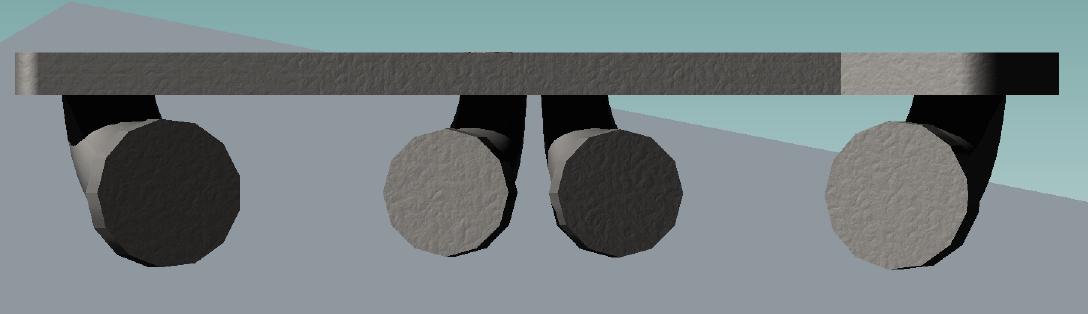
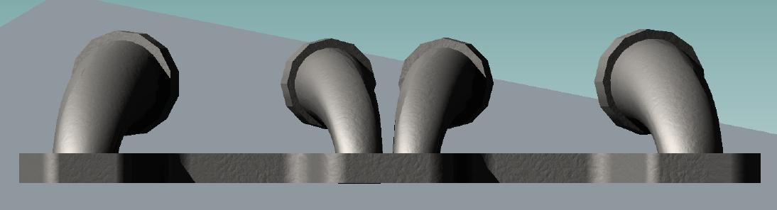
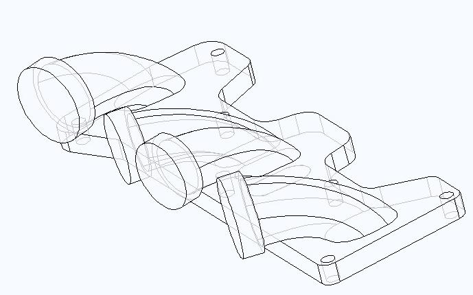
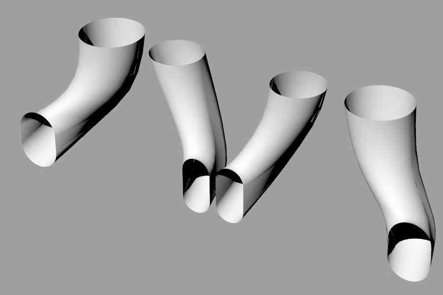
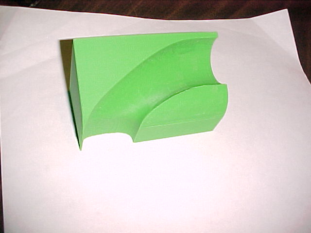
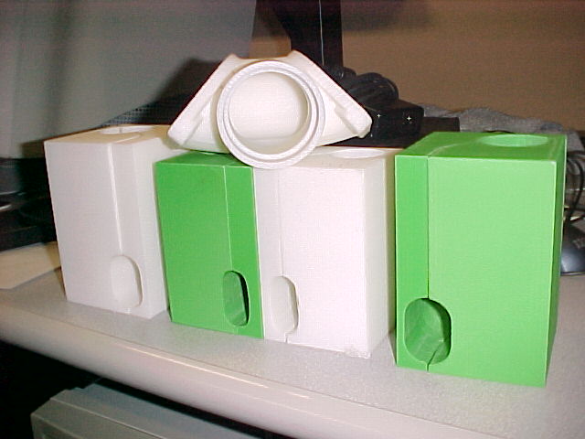
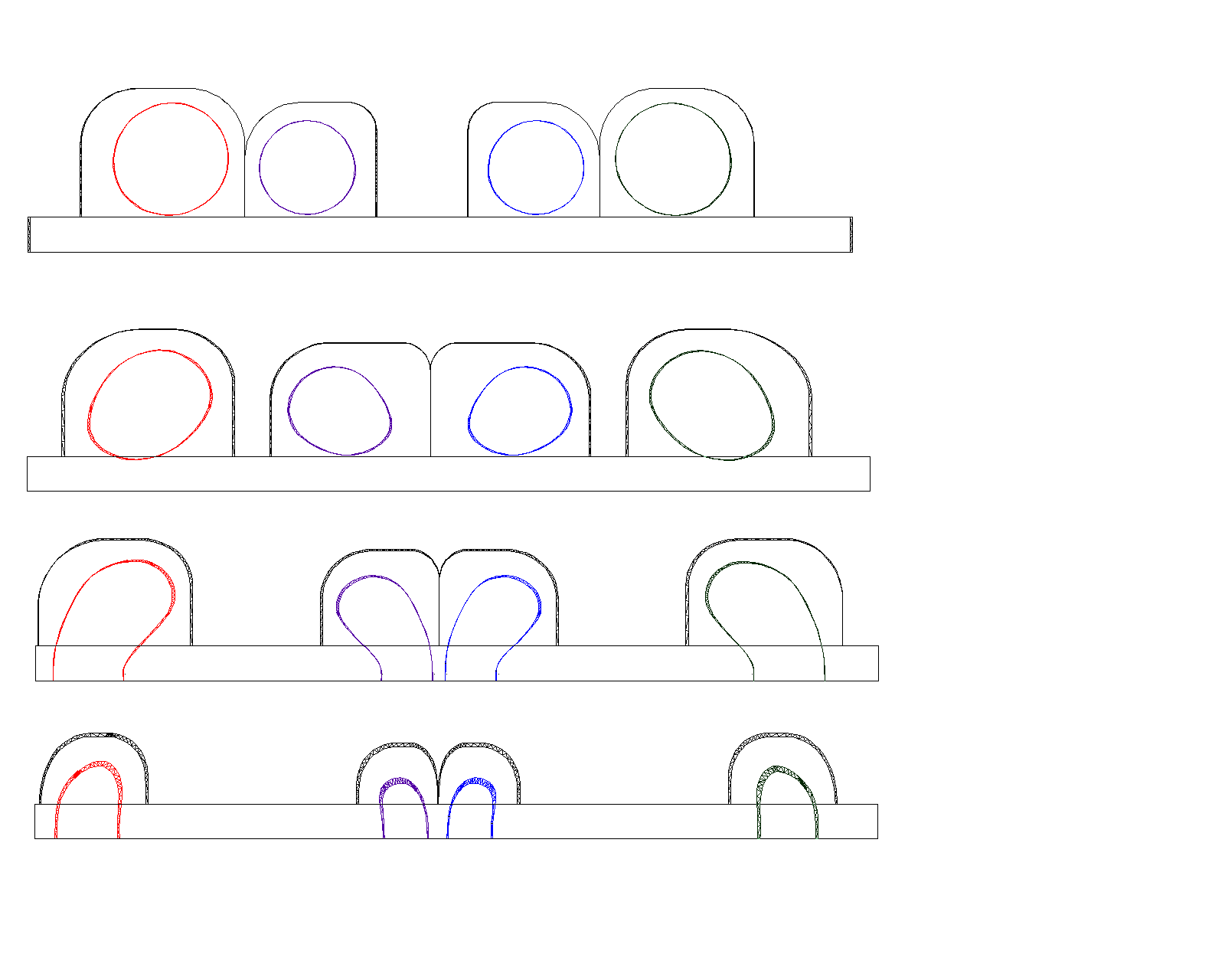
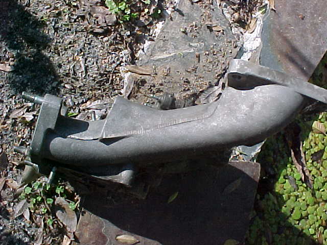
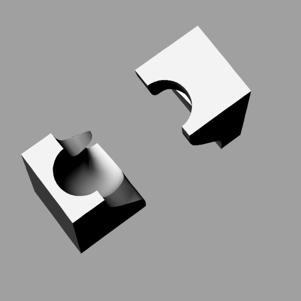
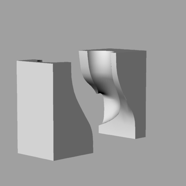
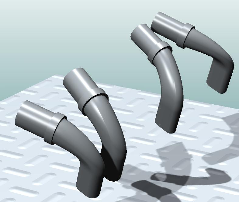
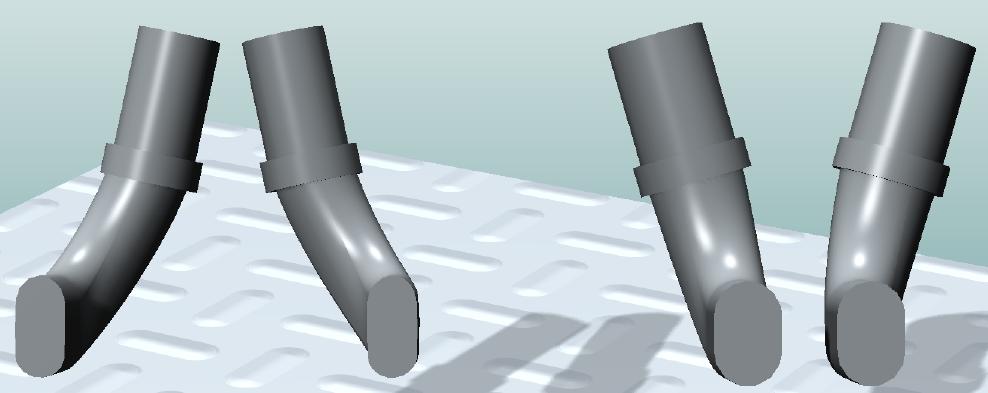
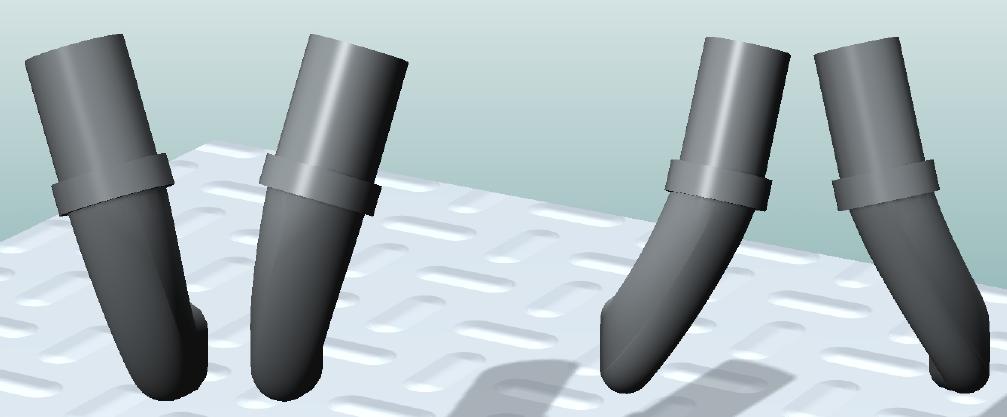
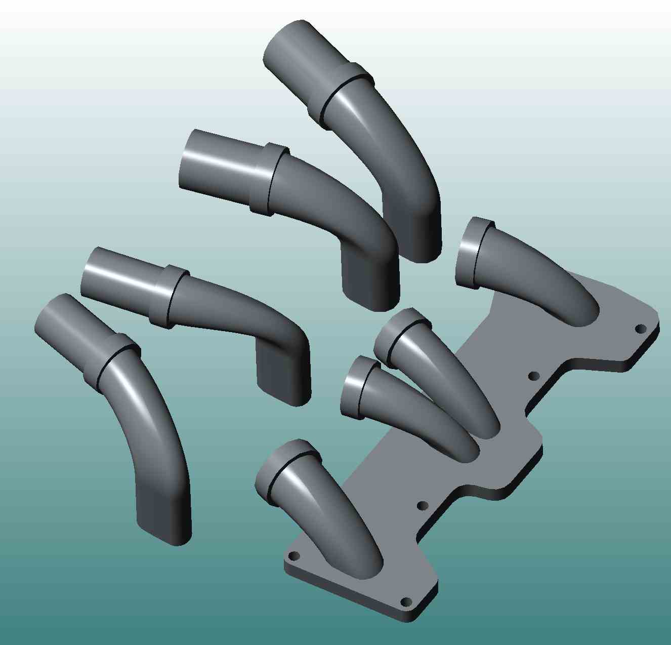
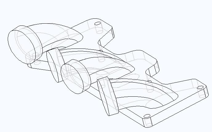
It is very thin. On the order of .065. Here is how Mazda does it.
You would be reinventing the wheel :)
Paul Lamar
Dale Davies, I don't think you need a housing to measure. There is
in the Kenji Yamagughi (sp) papers found on the rotaryeng.net
<http://rotaryeng.net>
<
http://rotaryeng.net site the formula for generating the shape
of the
trycoid housing. It is generated by the path of the 3 rotor tips
as they revolve while the eccentric shaft rotates. You can generate
cartesian or polar coordinates to as many decimal places as you
desire.
I think my desktop does to 27 decimal places but I have it set to 5
since that is ten times as accurate as CNC can machine and more
just increases the file size. A CMM (coordinate measuring machine)
is not this accurate.
If you change either the eccentricity or radius you will be
makeing a new trichoid shape that hasnt been produced and therefore
there aren't any parts to measure. The Lada and Chinese rotaries
both
use the Mazda dimensions. Curtis Wright has a vast number of
displacements for use as both engines and pumps.Some are six
feet tall
inside the rotor housing. They all seem to have the same ratio of
eccentricity to radius. If you increase eccentricity relative to
the radius you improve torque, however I suspect it will not have
as high an RPM as the current optimized dimensions. Changing the
ratio also changes compression ratio which will require building a
matching rotor with the correct combustion chamber depression. The
volume of the depression for a given compression can be derrived
from formulas posted on this site last year. If you leave the ratio
the same and go larger then the currently designed end housing
databases can be 3D scaled up in the X and Y dimensions with the
same Z saving some design work. Several of us have end housing
databases including Jeff and myself.
The problem with building rotor housings is the final finishing
steps. They need machined and lapped to .0001 accuracy. This is
currently done on specialty equipment and not likely possible
with normally available CNC machine tools.
Although scratch building a rotary engine is a huge task, by the
time you are able to fit lubrication and cooling oil flows and
coolant
glycol through the mechanical and structural elements of the
engine you will be better able to modify the available parts to
suit your needs.
george grimes
Hi
We tried this at Norton circa 1976, we squashed a tube down to an
oval shape, machined the Alum housing to match the Oval. then Kopp
ground the Housing shape, but even then we could not transfer the
heat away from the chamber, and the Air cooled engine would not pass
a hot stop test, even with the best oils of the day, if we carried
out an emergency stop from a sustained WOT and switched off and
left the motor to cool down, invariably the seals would stick and
blow pass would start, and this eventually caused the Rotor side
face to smear.
I agree with a lot of the comments, however would also point out
that the Seal nose Radius needs to be and was matched within the
geometry, on the Norton we changed from R=70, e=11.6, a=0.5 to R=69,
e=11.6, a=2.5 and this helped the chatter and apex seal spring wear
rate. with the original geometry lubrication the seal would wear in
quite readily to match the geometry, but it could never match
exactly, this caused a radial apex seal movement of around 0.007 "
can't remember exactly and seal would work this cycle four times per
seal rotation, when we went to Water cooled engines the seal spring
failure overtook the after bake problem.
With regards to Mazda, if it is not broken then do not try to fix it,
I visited the plant for a week in 1988 and admired the Engineering
immensely, I was allowed full access to the development facilities
and we had at least 3 engineering meetings within the week in which
we talked openly about our problems, both direction, I would not
elaborate on Mazda issues of the day even to this day as we made a
Gentleman's agreement not to digress.
Bob Rowley
Ex Chief Test rider for Norton Motors Ltd
over 1 million miles testing Wankel engines from 1968 (BSA) to 1993
Very impressive Bob. I toured the engine plant but not
the engineering labs.
Paul Lamar
Hi Bob,
Great information. All is appreciated. I am not thinking of fixing a
Mazda
that is not broken. My thoughts are that if people are building
parts for
their own use, make use of some of the new technology. Copy a 13A
engine as it
seems to have similar size to the 16X that is not available yet. The 16X
appears to have a rotor width that is the same as the 12A engines.
It should
be fairly easy to make the rotor housings 70mm wide. Shape the steel
liner and
cast the Al around it. The 13A's were 60mm wide, the same as the 10A.
The more people are thinking and chip in, the better probability
something
good is done.
If you guys were to have a clean sheet for design, what would you
like to see?
Low cost, light weight, reliability, simple are a few things. What
else the
conventional AC have that could be incorporated?
Dale Davies
Dale,
Things that we did for Manufacture.
We always programmed the CNC with the tool centre path but kept the tool
diameter down, commensurate with avoiding tool push off, generally less
than 2e.
We programmed the steps along the Housing / Rotor surface path so as to
avoid machine marks (similar to chatter) a the geometry formulae
produces a non linear step, we still used the Geometry for the Rotor /
Housing being produced, we adjusted the sizes by making changes to
Little a (Negative or Positive) to produce parallel undersize if
negative.
We used Ram Air on the Race bike, we was successful with this for a few
reasons, we put the Carburettor within the Ram air sealed Plenum
chamber, and the fuel tank connected to the Plenum, so the Actual ram
pressure was balanced within it own pressure, we used a simple dump
valve (flap of rubber), after the warm up lap you will see our riders
(in the early days) opening the Fuel cap for a few seconds sometimes
pretending to check for fuel level, (this stopped the engine flooding
and bogging down off the start), but in reality to put our competitors
off, as a few Japanese competitors was also trying to perfect Ram air at
the time.
The Rotary was a lot more forgiving of mixture strength than the
Japanese highly tuned four strokes, so this gave us an edge.
On the Racer we also used Exhaust ejectors to drag cool air through the
Rotor and crank.
With regard to the AC engine verses WC, the Norton, both types had total
loss oil, and this engine was perhaps ok for late 1980 it became obvious
that it could not be sustained for Road use, the oil usage was quite
low, but not environment friendly.
Housing, surface finish.
The Norton did not steel line, we machined oversize and plated then
final ground post plated housing, the speed of depositing was very
important to avoid subsurface stresses, this would manifest itself by
the plating pealing off on the change over from internal to external
shape, and if we was unlucky in service near the hot side.
Compression Ratio
When you make any changes to configuration, keep an eye out for the
Compression Ratio, I have an unproven (99 % sure that it's correct)
spreadsheet, that may help you if you do not have access to same.
I also have all of my own GWBASIC programs for Machine and Inspecting,
as by measuring with a dial calliper you can derive R+a' and e, but its
difficult to find the actual value of a,' for Racing the FIM allowed us
to ignore the actual value of Little a', as the pre or post race
inspection was interested in swept volume checking only.
I use to find the actual value by two methods, a Rotary table and
checking the vertical measurement at say 5 deg angles, knowing what R
and e was we could best fit the data to find the likely or produced a'
value, later we used a CMM and used a touch probe diameter that matched
the expected radius of little a'
Bob
From reading the above comments, can we actually re-chrome the old
rotor housing liners? Appears to me we can, if we can have someone
do it to a new liner, why not a used one?
If it were me, and I were willing to re-engineer the whole rotary
engine, I would start with designing a package sized between the
AIXRO, and a 13b. Designing a power plant with the same or similar
output as the 13b is'nt what I hear others needing. I do hear plenty
of requests for lightweight 100 to 150hp range.
So for me at least, I want to see if I can make a few prototype light
light alloy parts for the 13b. It is the size I need, and there are no
readily available light rotors or end housings priced low enough for me
to just go buy them. When I am finished satisfying my desire to
accomplish this; then on the the mid sized rotary.
Presently, we are already good to go with the standard iron side Pport
engine. So, next week, when all the metal suppliers are again open for
the new year, I'm digging into them for availability of our two,
presently most favorable, light weight alloys, the nasa 398, and the
beralcast 310.
While I'm at it, I will also determine the best method for making the
mold. If investment casting will work, I'm going for it. Then buy the
correct wax and go from there.
I will be posting for your input some ideas I have for additional
cooling of the rotor itself, in new alloy form, and hope we can come up
a durable design.
Ed Carver
Are you a pattern maker Ed? If so I might have some work for you.
Most pattern makers using traditionally materials charge a lot
of money for their art. It is a dieing breed as most new
casting patterns are made in NC machines. Core boxes are
particularly difficult to make as the wall thickness is very
difficult to control. I know. I have been there and done that.
Rhino 3D helped greatly but the biggest help was the
stereo lithography machine at Ventura College :) No longer
in operation unfortunately.
Paul Lamar
--
The Rotary Engine NewsLetter. Powered by Linux.
ACRE NL web site.
http://www.rotaryeng.net
Youtube key word PaulLamar2
Copyright 1998-2010 All world wide rights reserved.