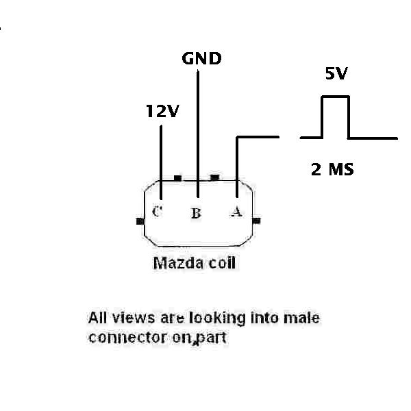
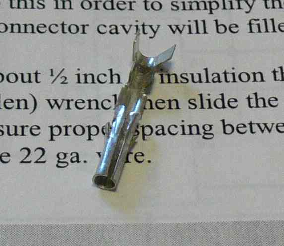
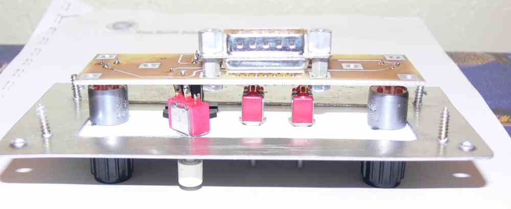
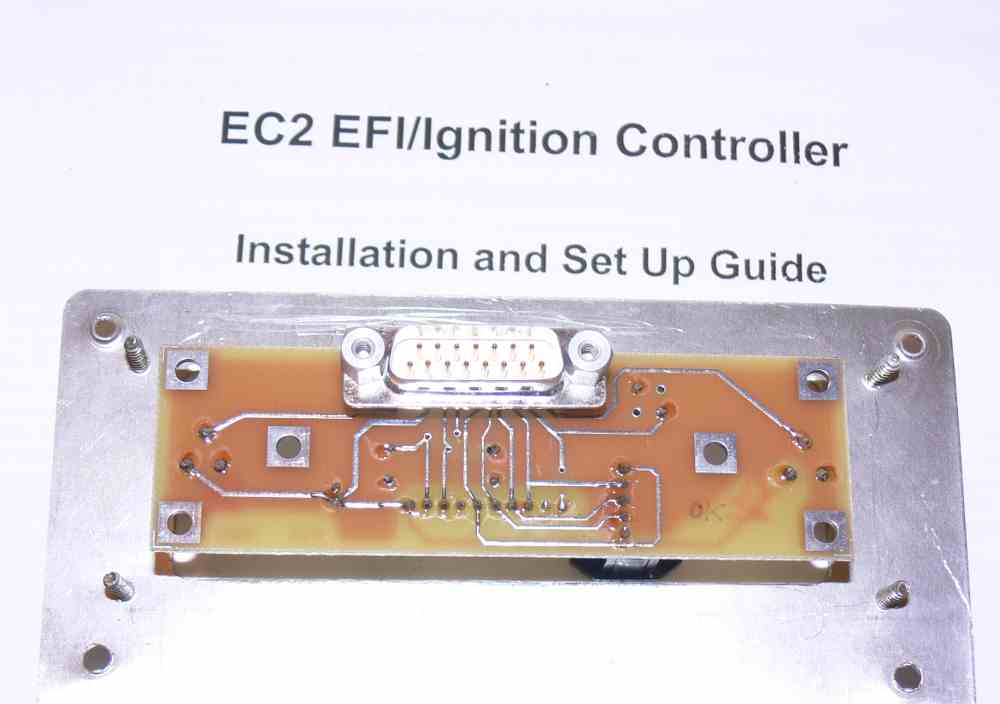
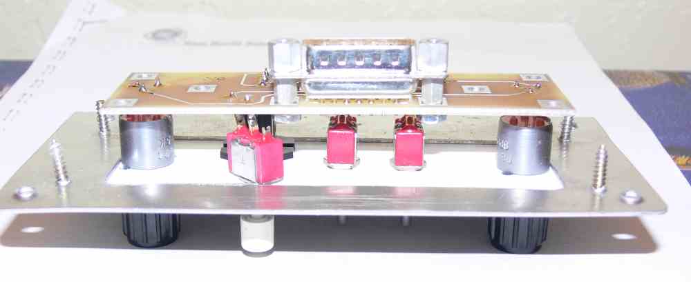
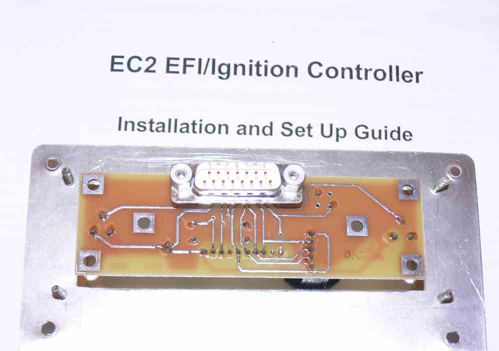
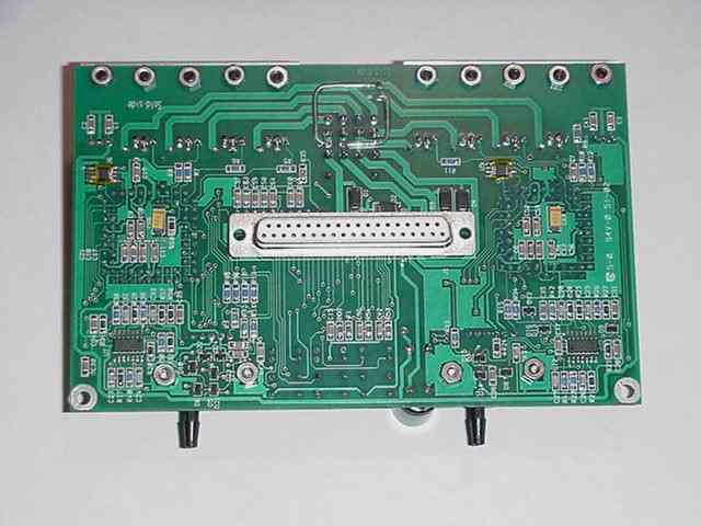
This is the second Tracy computer that I have wired.
I am now in charge of 3 of them. There is more to
this than just a schematic.
I decided to do a little preliminary planing to avoid
the rats nest result :) Hopefully this will
make it easier for other people to do it.
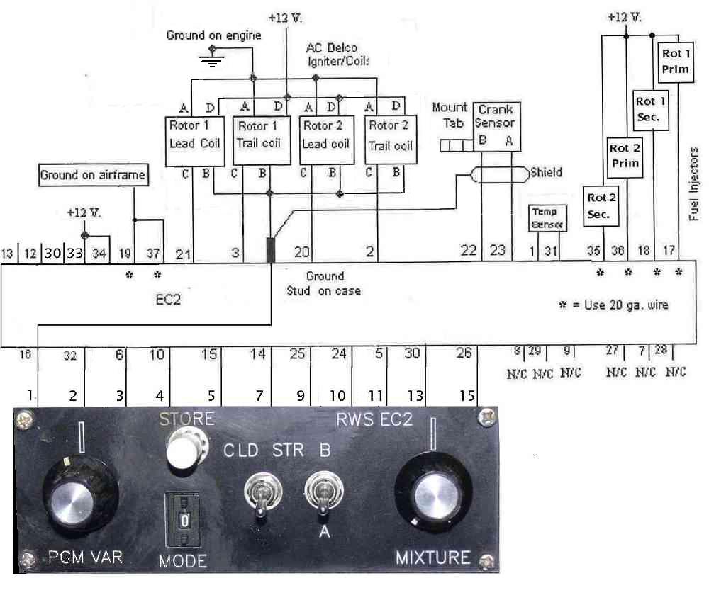
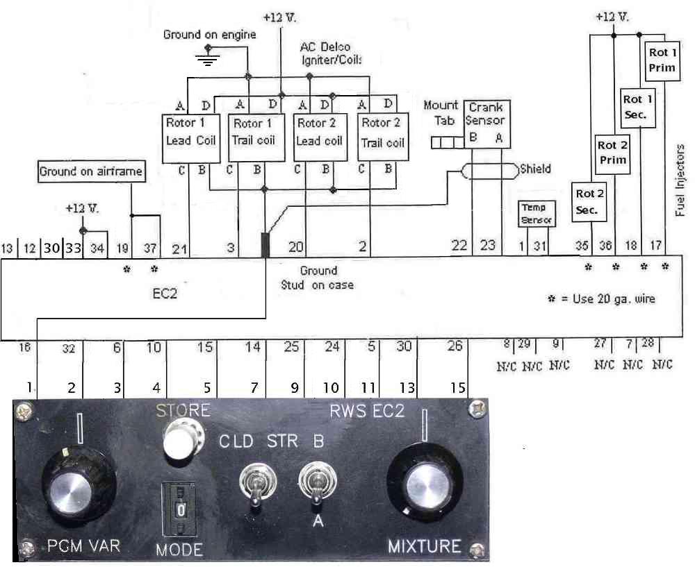
I also re-drew Tracy EC2 schematic to make it more clear.
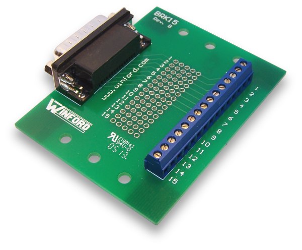
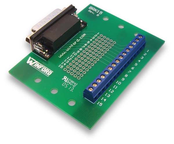
The PCM module has a male 15 pin D sub min connector
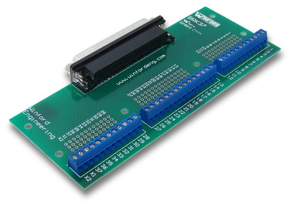
so I will order a female 15 pin break out board from Winford
Engineering.
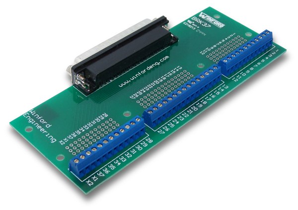
http://www.winfordeng.com/products/brk37.php
tomorrow. I did not draw or wire in the coil and injector disable
switches as I don't need them for the test stand.
Tracy recommends soldering to mating D sub min connectors but
unless you are a young, skilled electronics technician with good
eyesight that will be problematic. Therefor and hence the break
out boards.
Basically there are three wiring bundles or cables.
Cable 1 Injectors. 4 wires.
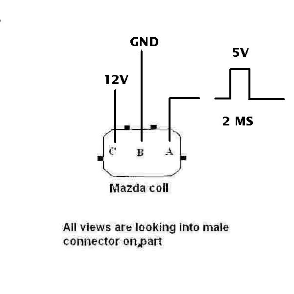
Cable 2 Coils. 4 wires
Cable 3 A user interface panel called the PCM with 11 wires.
Everything but the injectors are low current
five volt circuits so very small wire can be used.
One of the little tricks I discovered is buy old cheap parallel
printer cables. They have 18 wires in them, all of a different
color, shielded with a ground wire in a sturdy vinyl jacket.
They come up to 12 foot lengths. Cut off the connectors and
throw them away.
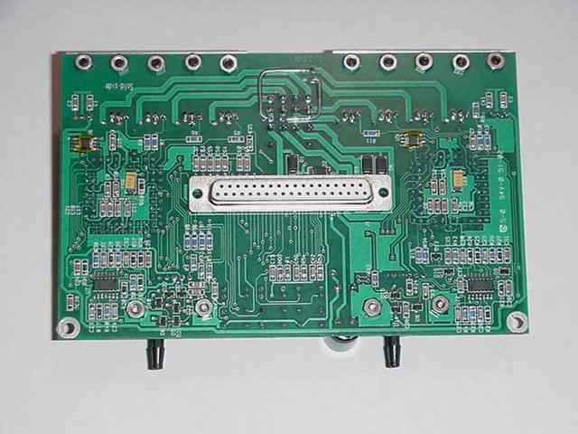
Ideal for the cable from the PCM to the EC2.
The wires from the EC2 to the coils are low curent
as well but there are only 4 so any old RS232 cable
can b used. These cables are obsolete for PC's so they should be
pretty cheap. The advantages of having the cable in a nice heavy
protective vinyl jacket are not all obvious. Finding unique colors
is less of a problem as each cable will have a limited number of wires.
The injectors are another matter as high currents are switched
by power transistors in the EC2. Tracy recommends 20 gage as
I recall so you will have to make up a cable with 4 color coded
20 gage wires in it. There is a product called Flex Guard Convoluted
tubing. That will take the place of the vinyl jacket and serve as well.
That can be bought from DigiKey or Fry's.
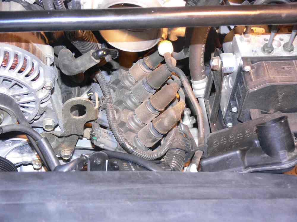
The key to this plan is all coils and all injector need
what Tracy calls switched 12 volts. All that means is you
cannot just connect the injectors and the coils to the battery.
It must be switched off when the master switch goes off.
The reason this is so is these device are also connected to
transistors in the computer that might leak current and
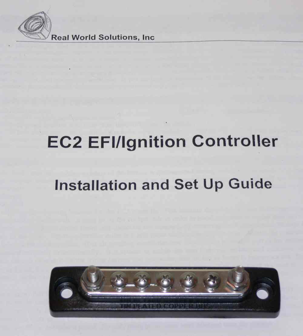
run down the battery. Therefor we need a fairly heavy wire
from the master switch to the top of the engine going
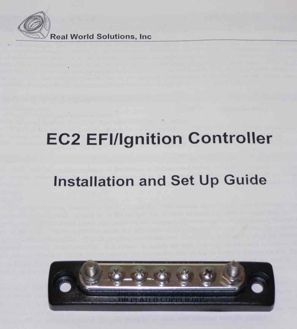
to a 12 Volt bus bar to supply both injectors and coils.
I found a boat bus bar that looks like it will work
great. Lots of boat stuff is higher quality than automotive
stuff.
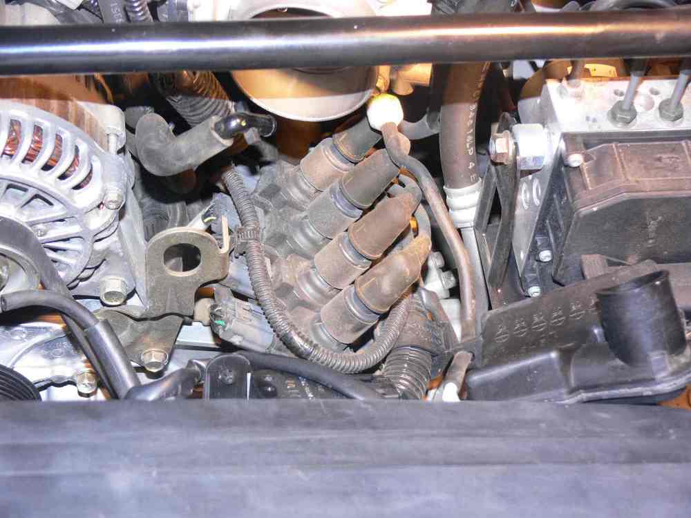
If that is made available on the top of the engine it would be
convenient to the coils and the injectors. Of course
engine ground will be there as well for the coils.
Hopefully I can make a large improvement in the neatness of
the ACRE test stand wiring. Also with the help of the break out
boards one should be able to wire this up in an hour.
Hopefully this is going to save you a lot more time
that that.
Wiring errors and failures are a major cause of
alternate so-called "engine" failures.
Stay tuned when I get this thread done with input from
the electronic techs on here and the test stand engine
running I will post it to the web site for future builders
using Tracy's computer.
Paul Lamar
--
The Rotary Engine NewsLetter. Powered by Linux.
ACRE NL web site.
http://www.rotaryeng.net
Youtube key word PaulLamar2
Copyright 1998-2010 All world wide rights reserved.