From past experience of piston cranks, I know they can be welded and
repaired. Now, the question, could I cut, weld, and heat treat two
13B cranks to make a four rotor?
Regards,
Norm P.
Well yes and no. Most 4 rotor e-shafts are three pieces.
Other wise you can not get the engine together.
You almost have to have taken apart and put back
together a 2 rotor to understand why.
Paul Lamar
Norm P. There is a lot you can do for drag racing that will not survive
in airraft use. The first problem is that a normally aspirated P-Port
four rotor is 500 HP at takeoff RPM and 440 continuous available
for cruise. With more gear reduction than 2.85 to 1 the horsepower
can be well over 600. Using the stock components lined up on a custom
eccentric shaft the cooling glycol goes from the pump through all
the side housings and rotor housings, then crosses across the rear housing
and back to the front housing outlet . As the water heats up progressing
through the assorted housings the cooling around the spark plug
area becomes inadequate resulting in detonation. The plugs, apex
seals and stationarg gears will have problems from the detonation.
There have been conversions of intermediate housings to allow
parallel cooling where the coolant only passes through a single
rotor housing. This is possible but the tension bolts and water
seal "O" rings limit the size of opening into the housings.
Second concern is balancing the e-shaft. Many people have
built four or more rotor engines with the eccentrics staggered 180
degrees to balance the rotating assembly with counterweights only
on the ends of the shaft. Theu use stock counterweights which are
also used as mounting flanges and spacers for other parts. If the
two intermediate eccentrics don't need counterweights then using
that same logic the end counterweights on a two rotor which is an
180 degree offset wouldn't have counterweights either.
The accessory pumps are also a problem. An oil pump designed
for a three rotor would be a stretch on a high output four rotor,
If all the oil was for lubrication of eccentric and stationary gear bearings
that would be fine. However 1/3 of the heat rejection of
the engine is from oil sprayed into the rotors and around the E-
shaft. As continuous power increases so does this need for heat
rejection. The three rotor water pump is also low on flow rate for
a four rotor which needs 50 GPM at full power. The pump has twice
as many passages to push the water through and therefore more back
pressure which will reduce the flow rateeven further.
There are several ways to address these issues. You can search
the Internet for the five rotor Curtis Wright aircraft engine which
might give some insight. Also on the Internet is Grannies speed shop
which close coupled two complete two rotor engines less one flywheel
and starter. This was raced in a circle track modofied. The stock
E-shafts were connected with a home made coupling. After you get
through Paul Lamars web site you should also go thru
Craigsrotarypage.com which has a lot of info particularly on the foreign
engines such as the Russian 3 and 4 rotors aircraft engines.
The basic Mazda parts are accurately described as robust as
evidenced by huge two stage turbochargers and NOS systems on drag racing
cars making 1600 HP. The cooling and lubrication issues of an
engine under load for seven seconds is different than hours at
near wide open throttle in an aircraft.
Personally I went with stacking complete engine rotating
assemblies with aluminum end housings, The rear or the front
engine and front of the rear engine have matching bell housings
located on dowel pins for alignment. The center housings are
modified for parallel cooling and extra fasteners are added. The
oil system is a 5 stage stock car gerotor type and the water pump
is 426 Chrysler big block. The designs are frozen, the G-code is
compiled for my CNC gantry router but I haven't built a test engine
yet. I plan on putting a six rotor in a 1965 E-type Jag with turbocharging.
George grimes
AA Drag racing engine frequently don't have any cooling what so ever.
The metal does not get a chance to over heat in 5 seconds.
One way to cool a four rotor is make all end an intermediate
housing two pieces NC furnace brazed together with parallel radial
cooling by external plumbing. The secret to making this work is monitoring
the rotor housing with four thermocouples mounted just below the lower
spark plugs sending info to four temp gages on the instrument
panel. Then tailoring the flow accordingly. Not a bad idea for a 3 rotor
as well.
Endurance racing Chev V8'a are frequently modified with parallel
cooling system using a plethora of external plumbing hoses.
The Orenda big block based Chev V8 $100,000 aircraft engine had
external parallel cooling galleries cast into a custom block design.
Paul Lamar
Paul, I am running the water in the center housings just below the
lower spark plug to an internal manifold. From there it divides and
feeds half through the front rotor housing and half through the
back. The end housing internal flow manifold distributes the return
to the center housing and is used to heat the cool side to reduce temperature
variations in the housings side to side. The water exits the top on the
intermediate housing to carry steam away.There is an obvious difference
in flow passage capacity in the stock housings shown in your
attachments.
There is about three times as much area on the hot side as
the cold side. As seen in the attachment only two thruholes go directly
into a rotor housing opening while 9 line up with the hot side
passages, On the face side which is against the rotor housing there
are recesses cast in the stock rotor housing which allow flow
around the intake port area to additional rotor housing coolant
passages. I have expanded on the recesses and added more area thru
the housing to increase flow back through the cool side of the
housing. This will not change the actual flow through the rotor
housing but will allow future increases. Several of the cooling
passages thru the stock rotor housings have bulkheads with smaller
thru passages to control flow rates and add turbulence. In future I
may drill out a percentage of blocked areas until the area is equal
in both directions. At that point additional end housing flow may be
useful.
I am using a balanced piston flow divider on the exit side
of the water flow where the two engine modules water combines to go
to the radiator. Any difference in flow pushes the piston towards
the low pressure side to increase area on the higher pressure side
until the flow is close to equal. There are no thermostats used.
I get the idea of the thermocouples to equalize cooling which
will be useful on a test stand. Trying to implement something to bias
the balanced piston flow control is doable if necessary. An adjustable
spring on each side of the balanced piston could be added and set at
maximum cooling load.
george grimes
Hi George,
I tried to search for the 5 rotor CW you mentioned and found nothing. I did
find a reference to 5 rotors at Freedom Motors which appears to have some
involvement with Moller. They mention up to 9 rotors but I could find no
specifics. Can you give a hint as to where to find the CW 5 rotor info?
Thank you,
Dale Davies
They do exist.
If I told you where Dale I would have to kill you :)
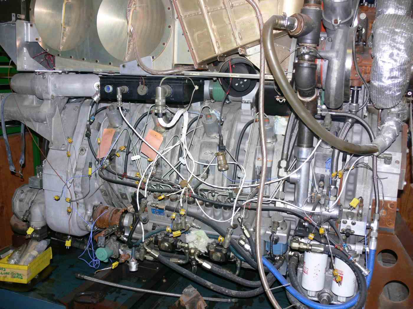
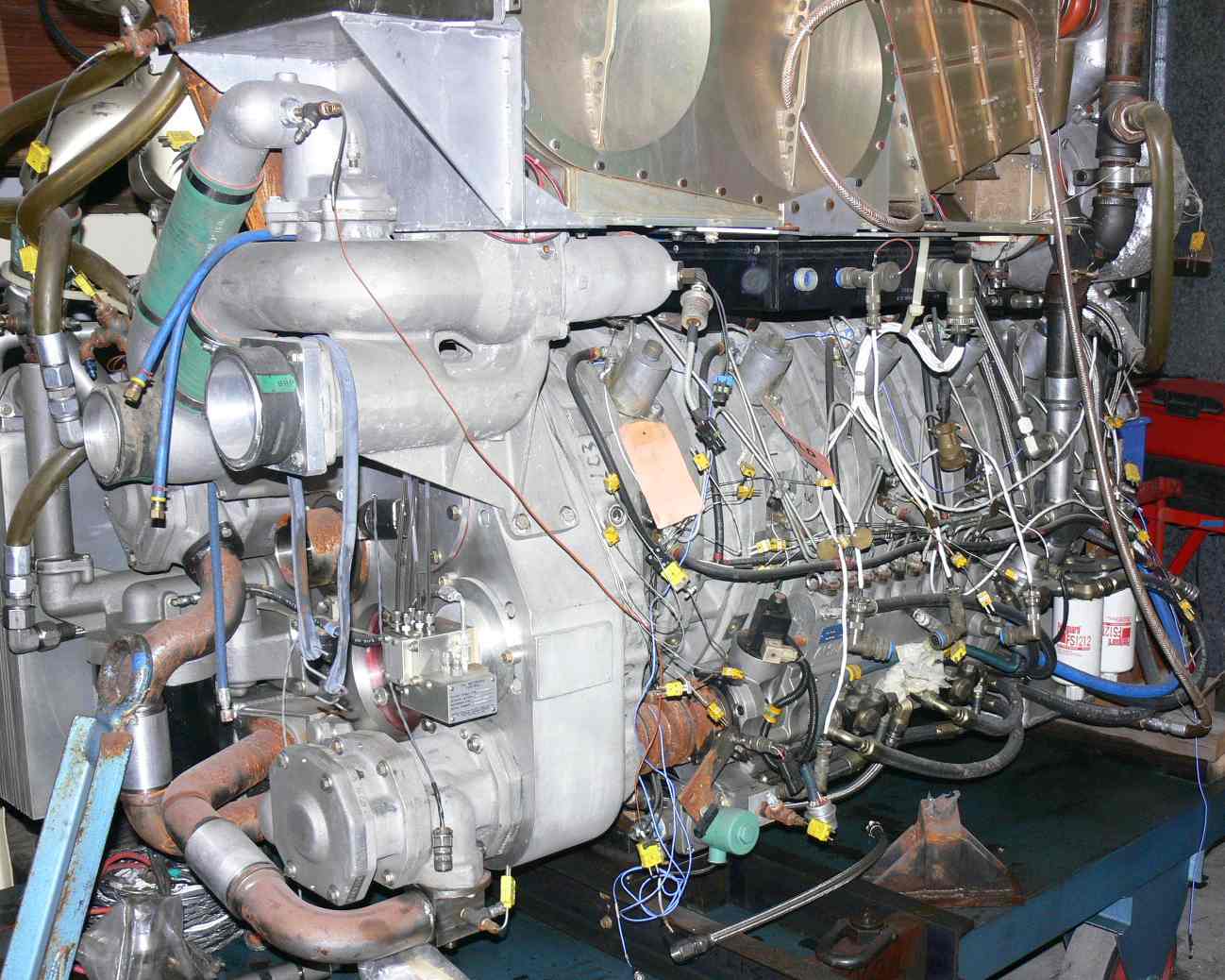
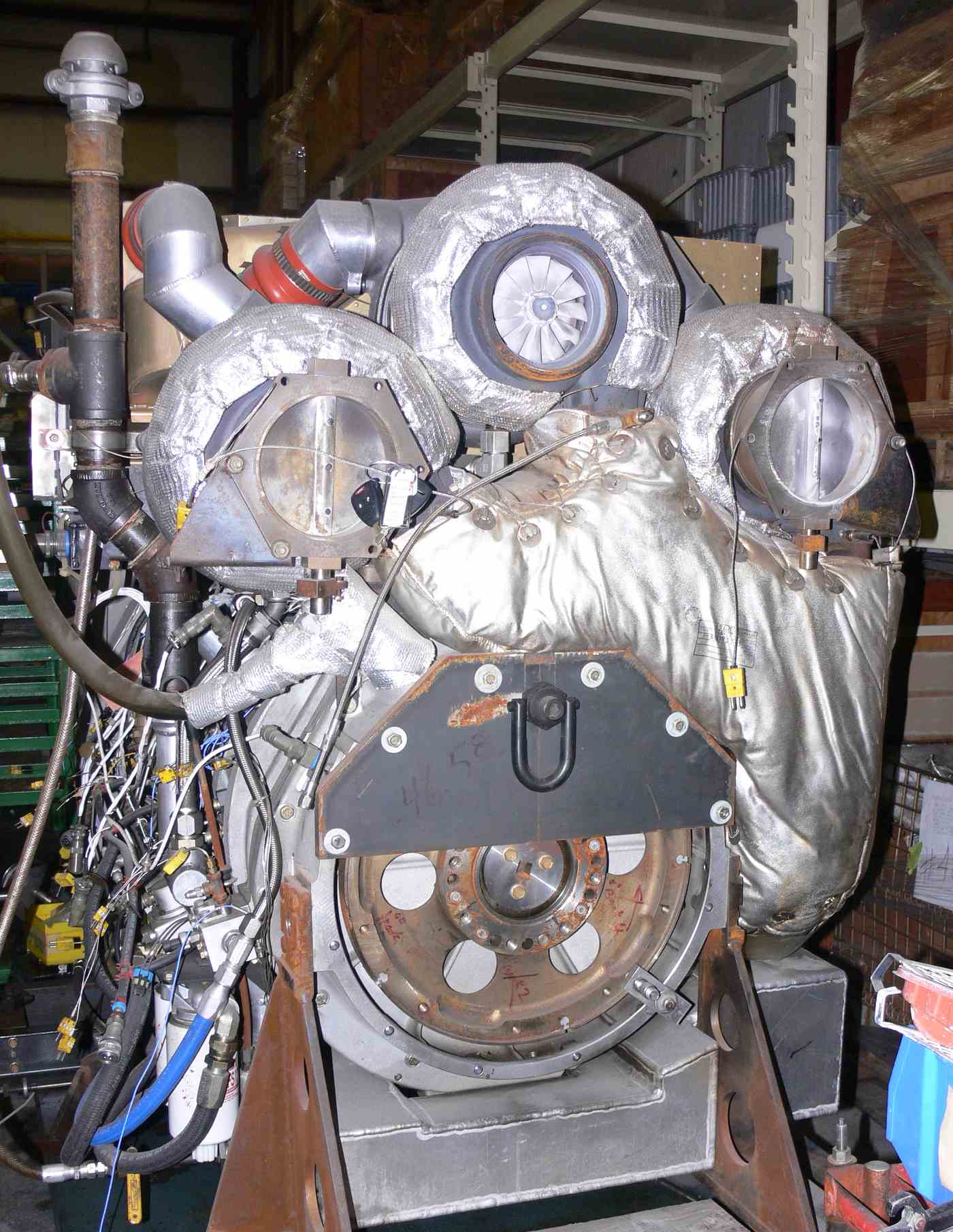
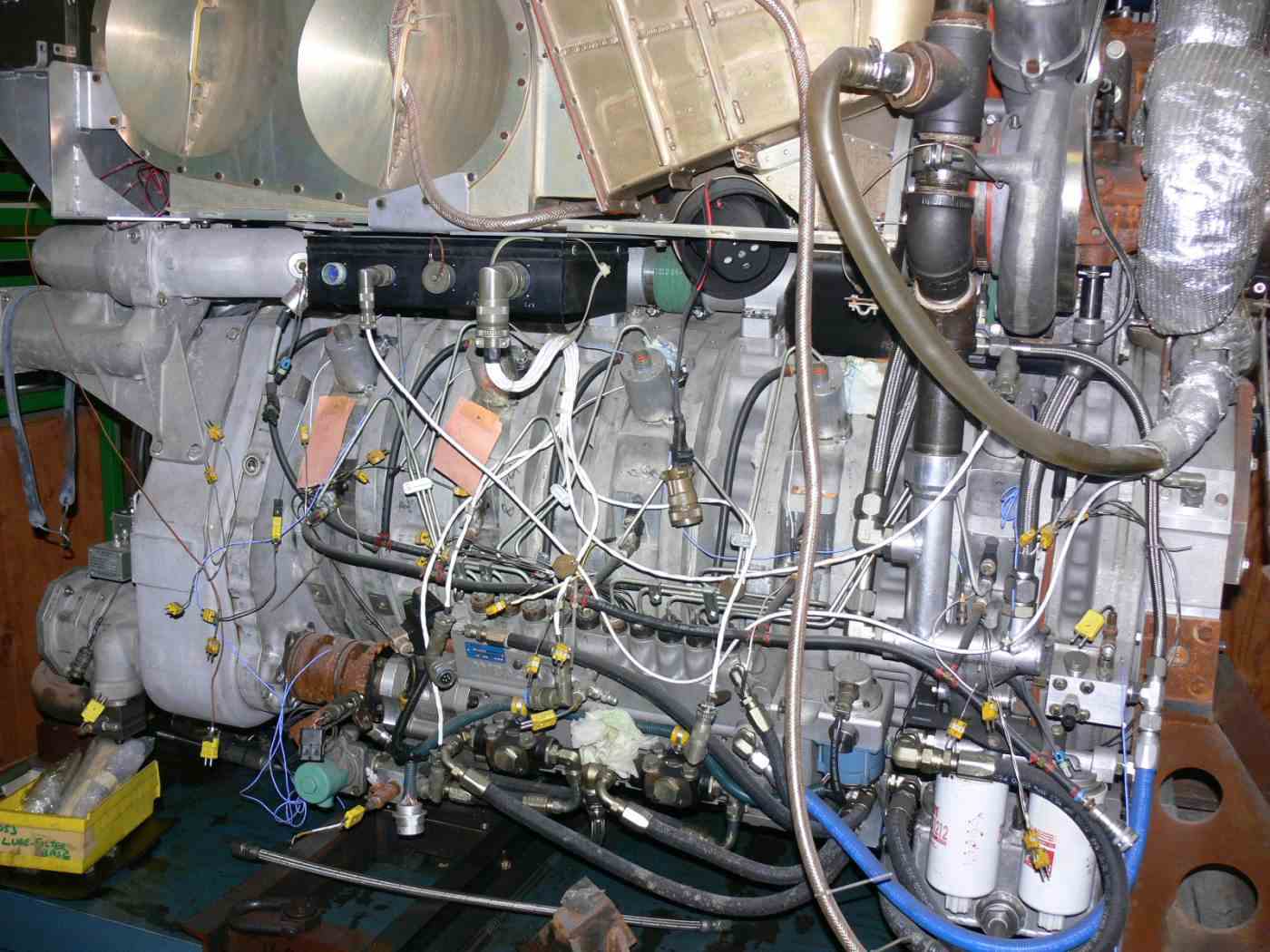
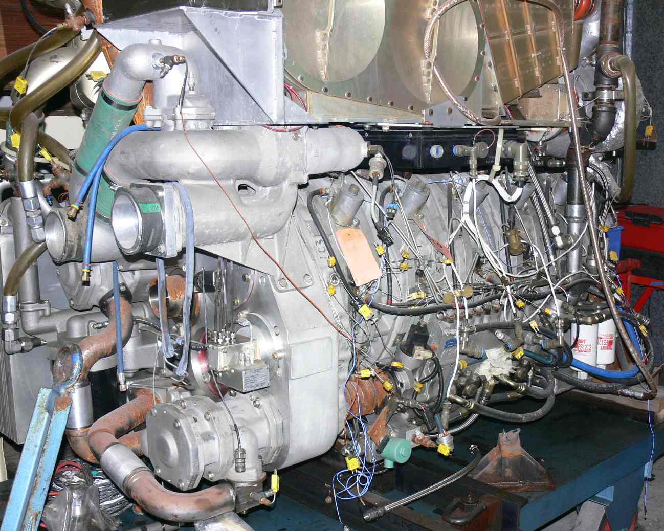
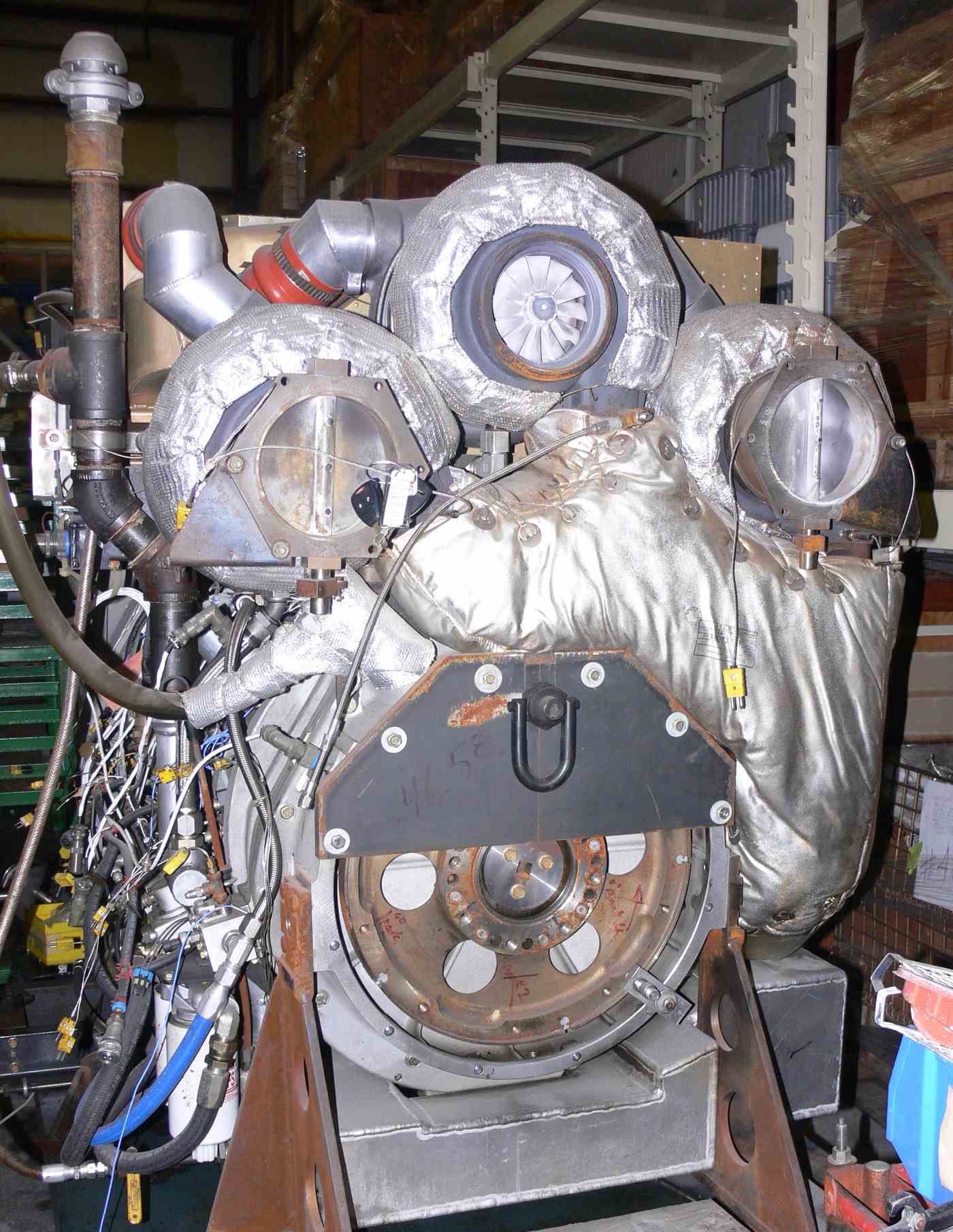
Here is a Curtis Wright 5 rotor in a secret location.
Paul Lamar
--
The Rotary Engine NewsLetter. Powered by Linux.
ACRE NL web site.
http://www.rotaryeng.net
Youtube key word PaulLamar2
Copyright 1998-2010 All world wide rights reserved.