This is the second Tracy computer that I have wired.
I am now in charge of 3 of them. There is more to
this than just a schematic.
I decided to do a little preliminary planing to avoid
the rats nest result :) Hopefully this will
make it easier for other people to do it.
I also re-drew Tracy EC2 schematic to make it more clear.
The PCM module has a male 15 pin D sub min connector
so I will order a female 15 pin break out board from Winford
Engineering.
http://www.winfordeng.com/products/brk37.php
tomorrow. I did not draw or wire in the coil and injector disable
switches as I don't need them for the test stand.
Tracy recommends soldering to mating D sub min connectors but
unless you are a young, skilled electronics technician with good
eyesight that will be problematic. Therefor and hence the break
out boards.
Basically there are three wiring bundles or cables.
Cable 1 Injectors. 4 wires.
Cable 2 Coils. 4 wires
Cable 3 A user interface panel called the PCM with 11 wires.
Everything but the injectors are low current
five volt circuits so very small wire can be used.
One of the little tricks I discovered is buy old cheap parallel
printer cables. They have 18 wires in them, all of a different
color, shielded with a ground wire in a sturdy vinyl jacket.
They come up to 12 foot lengths. Cut off the connectors and
throw them away.
Ideal for the cable from the PCM to the EC2.
The wires from the EC2 to the coils are low curent
as well but there are only 4 so any old RS232 cable
can b used. These cables are obsolete for PC's so they should be
pretty cheap. The advantages of having the cable in a nice heavy
protective vinyl jacket are not all obvious. Finding unique colors
is less of a problem as each cable will have a limited number of wires.
The injectors are another matter as high currents are switched
by power transistors in the EC2. Tracy recommends 20 gage as
I recall so you will have to make up a cable with 4 color coded
20 gage wires in it. There is a product called Flex Guard Convoluted
tubing. That will take the place of the vinyl jacket and serve as well.
That can be bought from DigiKey or Fry's.
The key to this plan is all coils and all injector need
what Tracy calls switched 12 volts. All that means is you
cannot just connect the injectors and the coils to the battery.
It must be switched off when the master switch goes off.
The reason this is so is these device are also connected to
transistors in the computer that might leak current and
run down the battery. Therefor we need a fairly heavy wire
from the master switch to the top of the engine going
to a 12 Volt bus bar to supply both injectors and coils.
I found a boat bus bar that looks like it will work
great. Lots of boat stuff is higher quality than automotive
stuff.
If that is made available on the top of the engine it would be
convenient to the coils and the injectors. Of course
engine ground will be there as well for the coils.
Hopefully I can make a large improvement in the neatness of
the ACRE test stand wiring. Also with the help of the break out
boards one should be able to wire this up in an hour.
Hopefully this is going to save you a lot more time
that that.
Wiring errors and failures are a major cause of
alternate so-called "engine" failures.
Stay tuned when I get this thread done with input from
the electronic techs on here and the test stand engine
running I will post it to the web site for future builders
using Tracy's computer.
Paul Lamar
Check out this YouTube comparison of the LS1 & LS2 "Yukon" coils.
http://video.google.com/videoplay?docid=-6218245369765754251#
Mark
Remember the V8 engine fires every other rev while
the RX8 coils fire every rev. Not only that the RX8
coil need to fire at 9000 RPM while the V8 6500 RPM.
a 5 millisecond dwell is marginal for a rotary
at 7500 RPM.
My hopes are on the second gen RX8 coils.
Paul Lamar
--------------------------------------------------------
I am rapidly discovering these older RX8 coils are very
sensitive to exact routing of the trigger, ground and power
supply wires. I think a large capacitor would help on
top of the engine from the switched 12 Volt supply to
engine ground. The trigger wire from the EC2 to the
RX8 coil must be well shielded. 2 ms was inadequate
for a stable trigger so I upped it to 3 ms.
The failure mode seems to be double or triple
trigger. That drastically increases the dwell time
over heating the coil.
Now it could be the spark is out in the open and that
could be part or all of the problem. With the spark
inside the combustion chamber it could be a whole new
ball game. I won't know until I get this system
running. Early Morse code radio transmitters were
merely spark gaps. dot dot dit dit.
If you crash in the wilderness take one
of these coils and make a spark transmitter with
a long wire antenna. It will go out over a wide range
of frequencies.
I also don't know what Tracy is using for
a dwell time. I did see 20 ms at cranking speed.
If that is the same dwell at 7500 RPM that would
be a disaster of the highest order for any coil.
Tracy, what is the dwell at 7500 RPM???
At 7500 ms we have only 8 ms to work with.
In other words that spark plug must fire
every 8 ms. That is not a lot of safety margin.
Since just about everybody agrees the GM coils
require 5 ms so I don't think they are a good
idea regardless of the generation. LS1, LS2 etc..
In the Chev V8 at 6500 RPM the GM coils are only
required to fire every 18 ms. In other words
every other rev.
I do hope the 2nd gen RX8 coils are going to work
better and I am supposed to get a set today.
I am also going to get Jeff to make up a heat
sink to mount the RX8 coils. It will require
a clamping bar so the connector end can be in
good contact with the heat sink. You will be able
to buy it directly from Jeff.
Here is a good extrusion to start with.
Should be 8 inches long with the coils
mounted cross wise on 2 inch centers.
Send your coils to Jeff and he can take
a clean up cut on the bottom to make
close contact with the heat sink.
Use heat sink grease to mount the coils.
Paul Lamar
A marked reduction in false triggering should be obtained by wiring a 1k
resistor from trigger lead to ground at the coil. The trigger input
impedance is very high, so the resistor gives several orders of
magnitude reduction in the stray noise voltages. I have observed the
same condition in testing the LS coils.
Victor
Good idea Victor. Makes perfect sense.
BTW Think how many engines and millions of dollars Mazda would
have saved if they had done that.
The law of unintended consequences:
A. Raise the red line to 9000 RPM.
B. Redesign the coil so it will work at 9000 RPM.
C. Cut the oil supply to the rotor housing to reduce HC.
D. Change the exhaust to side exhaust.
E. Use 2 oil injectors per rotor rather than one.
Result: Engine mysteriously starts failing at 30,000 to 60,000 miles
while before they would go to 300,000 or 400,000.
Reduced oil injection suspected.
Coils start failing.
Redesign the coils.
Increase oil supply to the injectors program change.
Increase engine warrantee to 100,000 miles and eight
years.
Problem does not go away?
Missing 1 cent resister!!!
Paul Lamar.
Not at my work computer right now so this is off the top of my head.
All the coil options have different dwell times. The Renesis coil
option is about 2.6 ms. I'm not sure that option was even available
when your EC2 was made. There have been a LOT of changes since then.
Starting dwell (< 600 rpm) is much different and not accurately
controlled. but around 10 - 20ms depending on cranking speed.
Tracy
Thanks Tracy. No telling what I have but I think it was sold back
around 2006 and sold to Milo Burroughs. I'll measure the dwell when I get
it running shortly as fast as it will go with the intake and IVO prop
I have. 2.5 ms sounds great but a bit on the short side. I think
a good heat sink will allow a bit longer dwell.
Paul Lamar
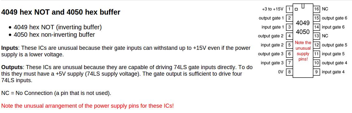
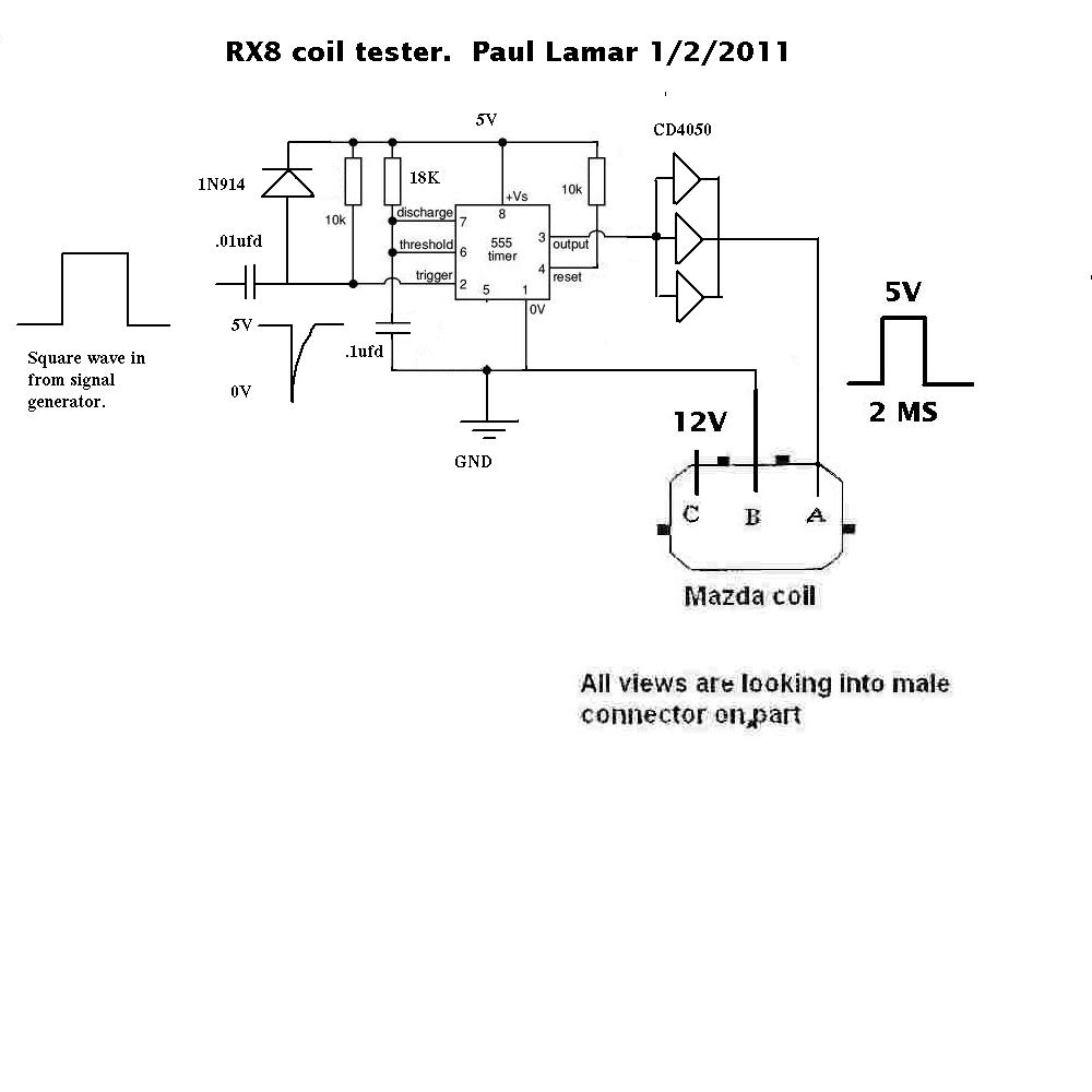
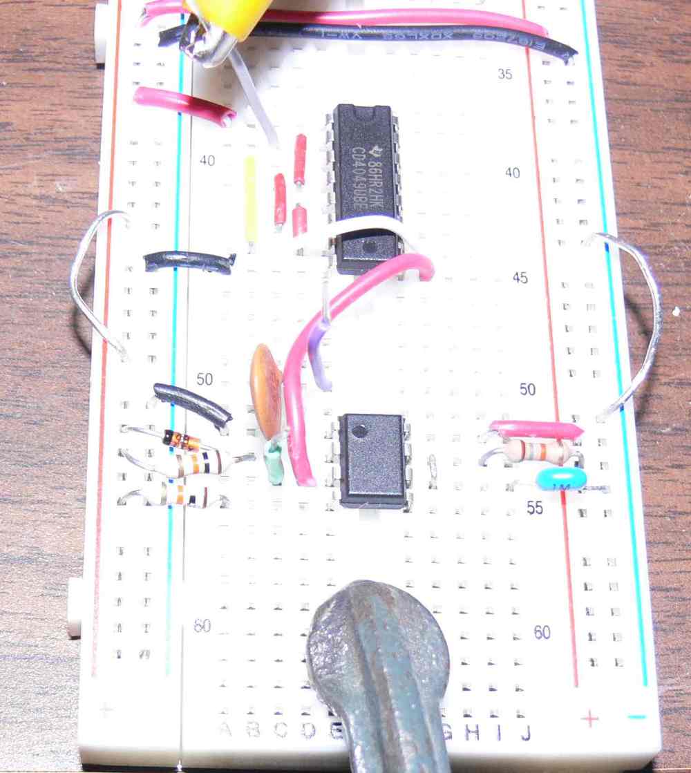
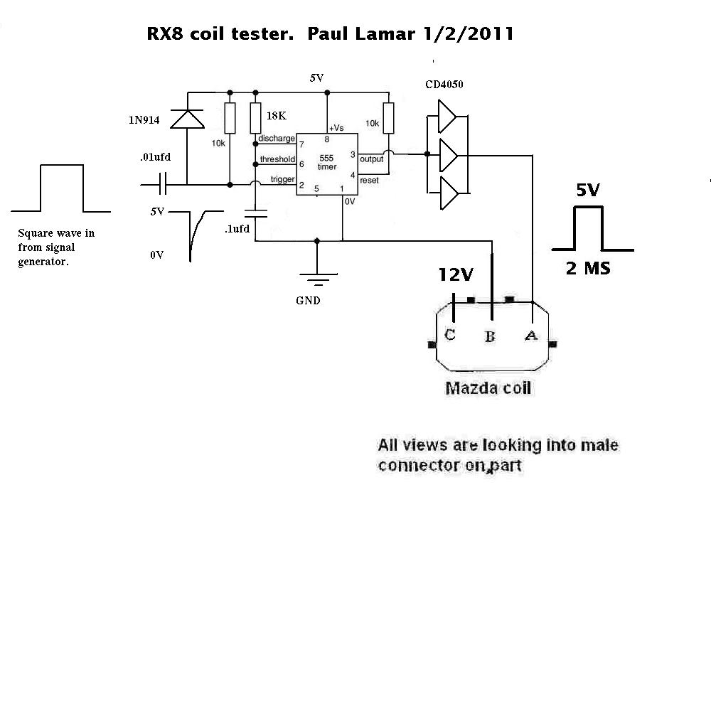
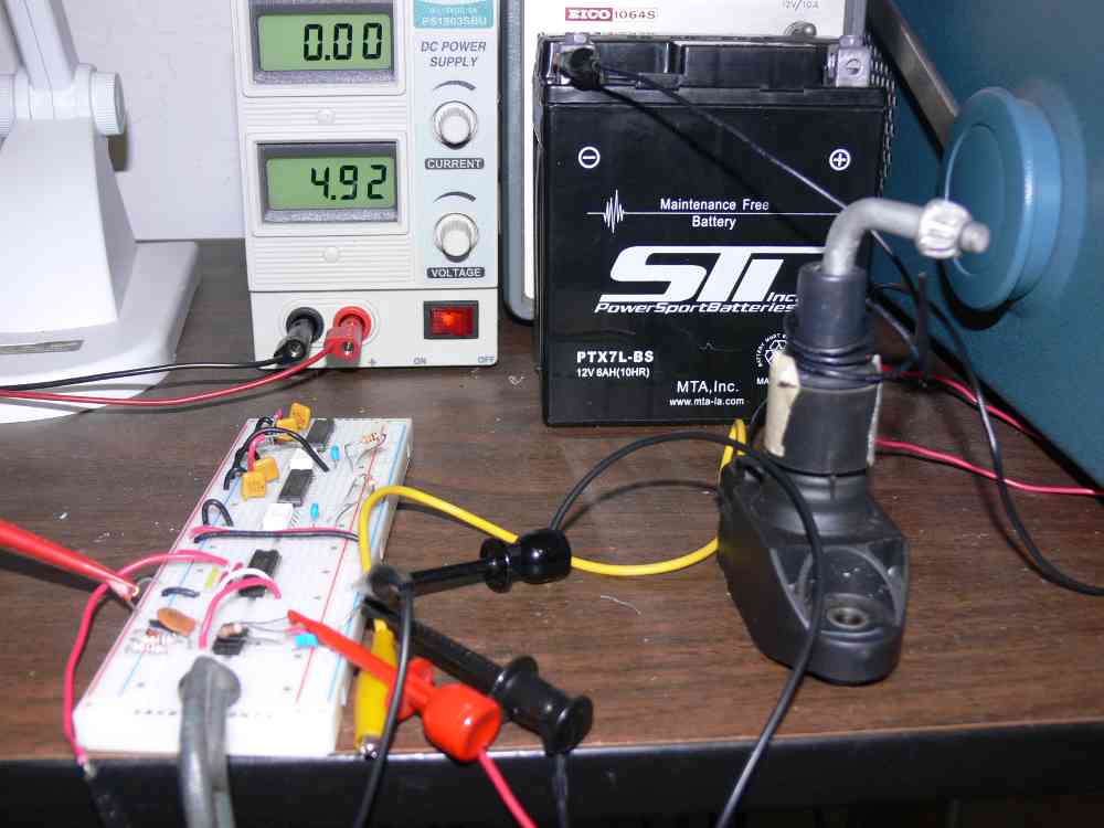
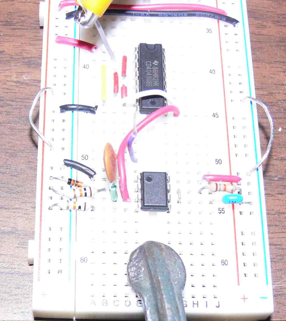
I tried the 1 K resister trick suggested by Victor at the out put
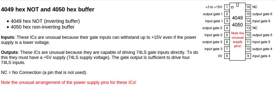
of the CMOS 4050 three gates in parallel and it did help. I know
that is not the optimum location but I did it to
check the drive of the 3 CMOS gates and it was easy and
quick. The trigger voltage dropped to about 2 volts down
from about three so more drive is called for. I can add
another three CMOS gates in parallel unless someone has
a better idea.
BTW from the modified shape of the trigger pulse the transistor
inside the coil looks like an FET.
I'll rewire the coil yet again and put
the resistor where it belongs at the input to the coil.
Tracy may need to redesign the coil drive as I have
no idea what he is doing now in that regard. Another
possibility is a stand alone low impedance coil driver box.
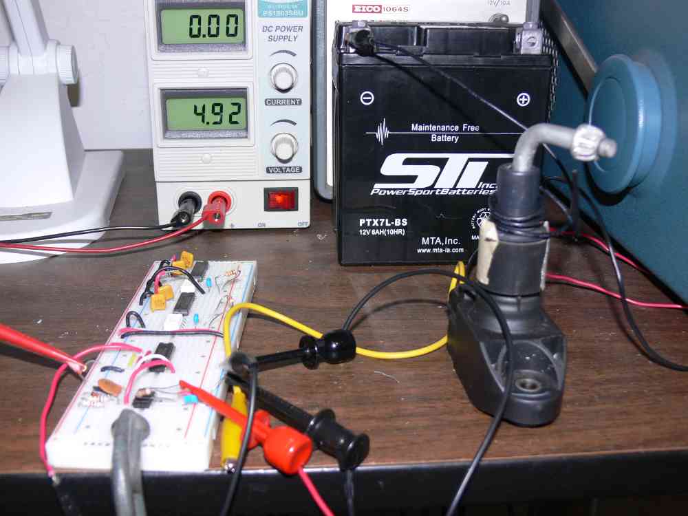
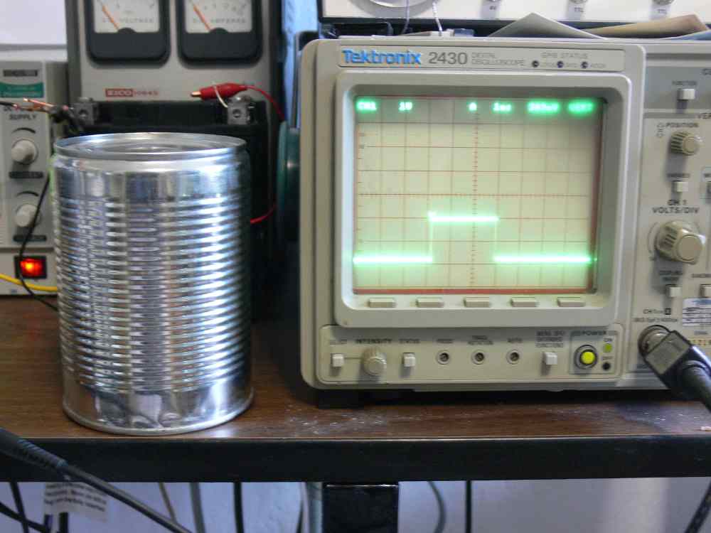
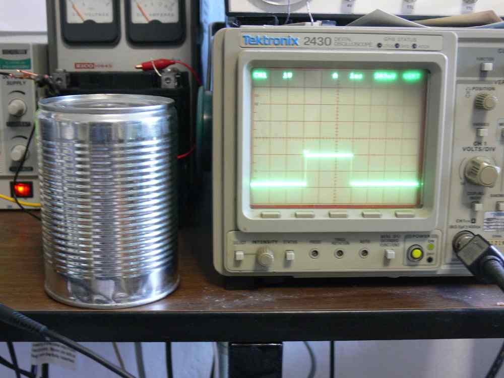
The other thing I tried was putting the coil in a soup
can. That helped as well so the problem may not be
as bad as I thought once the plug is inside the engine.
Kind of fun as the can acts as an audio amplifier :)
What makes this different from the car is Mazda builds
a prototype and tests the heck out of it to perfect
everything including the exact placement and configuration
of the wiring harness. Then millions are made with the exact
same harness arrangement unlike an experimental aircraft.
BTW new people don't freak out about the volume of emails.
Make a folder or folders in your email program and drag
this stuff over to be read later when you need it.
Paul Lamar
--
The Rotary Engine NewsLetter. Powered by Linux.
ACRE NL web site.
http://www.rotaryeng.net
Youtube key word PaulLamar2
Copyright 1998-2010 All world wide rights reserved.