As you are setting up the test engine, I would like to suggest a
couple of ideas which grew out of my study of your excellent work in
measuring MAP using the oiling holes, along with the improbable injector
maps others have arrived at for Tracy's ECx computers. Your
measurements showed the enormous variations occurring for each
combustion cycle.
I believe it is likely that these variations,
transmitted through small tubing, account for drastic variations in
measured pressure as standing waves are set up in the tubing which move
with rpm changes. The standing waves either add to or subtract from the
average pressure, and as rpm changes the measured pressure varies.
I first recognized problems in electronic measuring of MAP several years
ago when I bought an electronic engine monitor from one of the first
small vendors fo such items, and found MAP readings not in agreement
with my mechanical gauge. I tested both on the bench with our altimeter
calibration equipment, and they agreed. In the airplane, at low
altitude one read 20.0 when the other read 21.5. At higher altitude,
the error was reduced.
I added a restrictor to the MAP line, and the
error was further diminished. I was surprised at the degree of
restriction required to eliminate the error. My assumption was that the
system used an algorithm that produced a stable but inaccurate reading
for a varying input. A couple of years later I installed a Dynon engine
monitor in another airplane, and found the MAP reading very jittery. It
appeared they rapidly read and display a couple times a second, and each
sample varied from the previous.
Again, a restrictor solved the problem
Teeing the two pressure taps of a rotary does not eliminate the problem,
although it might reduce it. The very sharp drops in pressure during
intake mean either a very tiny hole in the tap or a substantial volume
in the lines will be needed to provide a stable pressure free from the
effects of standing waves. A separate line and accumulator to each MAP
sensor of the EC2 might be the best solution.
If my deductions are in error, perhaps some of the engineers here
familiar with fluid dynamics can set me straight.
Victor
Your basic reasoning of as to why there would be different readings
seems to hold water.
Any combustion engine that is not continous, ( jet , turbine, engine )
will produce it's vaccum in pulses. Even as the theoretical number is
known, the true intake pressure will be a wave of rising and falling
pressure.
For the engine this is actually a good feature, and we want it, intakes
are made with intake runners, tuned to the best performance, meaning, we
really want the air column to stack up against the next intake opening,
and give a superficial boost to fill the combustion chamber at the next
intake stroke.
And yes, this will be a conflict, with pressure readings, if we want
them as even and straight as possible, because the pressure sensor will
not read the theoretical average intake pressure, it will read violently
swinging ups and downs.
There are as you say ways to dampen the effect, by either restricting
the flow, to the sensor, but you will pay in slower readouts.
You put it close to the intake port and you will get a very quick
readout, but instead a heavier pulse. You put them close to the
beginning of the intake runner, and the pulses will be somewhat
smoother, but now you pay in slower reaction time.
Depending on how much you want to put into it, there are ways to get to
an equilibrium, a four cylinder engine, would have four intake runners,
a small tube from each one of them at the same location of each, that
will get to a spot in the middle will have equilibrium ( not fully of
course, but close enough) and I dont know rotaty engines that much, but
if it has an intake for combustion, that opens and closes, the basic
principles would be the same.
Lets say a two rotary intake pipes are running paralell, a small pipe
inbetween will give you that( lesser so the lesser combustion chambers
you have, that are loading up) ....but here is the clincher...only at
a certain spot at a certain RPM.
I'm sure yo don't want to drill forty seven holes in your intake
runners, just to find that spot, it's just not worth it....it's only
good for a certain RPM on top of it all.
Some kind of dampening or restricting arrangement is probably best, all
of them will make you pay with a slightly slower readout, but that is
the price.
One way to go here, ...if I may....just a sugggestion, as you have
experienced that it takes an extremely small hole to restrict the
pressure sensor, maybe , if the pressure sensor had a little chamber
ahead of it, that was internally designed for good flow, but, as a
muffler was designed to stop shockvaves.
I'm thinking...and this is highly experimental now....a muffler, has
actually very good flow though it, and that is what we want, that will
fill up and make the pressure sensor, feel the pressure quick. If we
just make the ebb and flow slow down, with baffles. so if we go the same
way, have a fairly good flow to the pressure sensor, that will enable it
to quick reaction time, as we have bigger holes, we have now gone away
from the very small restricting holes, but are aiming each shockwave
towards maybe a series of small baffles that can prolong the effect of
the shockwave long enough for the opposing wave force to take effect.
I'm not thinking about something that has the size of a regular muffler,
more the size of an ordinary D cell battery.
Lets say you have seven or eight walls in that cylinder, with seven or
eight 1 mm holes, (Here you need to experiment) in each wall that does
not correspond to each other, that's a lot of caivities and holes for
the shockwave to find. It will probably work better than a muffler, as a
muffler is a flow through system, while this is a dead end system, once
the "MAP muffler" is filled, it will now be a standing wave flowing back
towards the next oncoming shockwave.
The closer to the intake manifold the more of a standing wave, the
closer to the sensor, the less of a wave, if any. The object would be to
get no wave there.
There might be some experiments involved, but I am pretty darn sure
that will stabilize a pressure sensor.
It might also be an idea to look at how gun silencers are made, they
have come up with some pretty nifty technologies in that field, and
still they have to have a big huge hole in the middle of it, to make the
bullet go though, but they for sure have managed to treat that shockwave
in a favourable manner. Maybe some of that technology can be applied
between the intake runner, and the pressure sensor.
You want as much airflow as possible for a quick reaction time, but as
much as possible of the shockwave to dissipate, those two desires have a
tendency to not agree, so inbetween there somewhere is a compromize you
just have to experiment with to find.
Roger
It would seem to me that the
/time constant/ of the orifice and volume
of the system after the orifice must be long enough to cover several
cycles at the lowest rpm to be used in order to provide a stable
measurement of pressure. A pressure sensor at the end of a conduit can
only sense the pressure at the opposite end when there is no net inflow
to or outflow from the conduit. Therefore, the measurement must average
over at least one cycle for a constantly changing pressure, and as a
practical matter over several cycles. My intuition suggests to me that
this pressure would actually be the root-mean-square (RMS) value and not
the arithmetic mean, but either would only be an approximate and not a
precise indication of the mass of the charge.
Ideally, the pressure sensor would be located directly in the wall of
the combustion chamber, and the sensor would be connected to a
peak-sensing amplifier. The pressure in the chamber would be directly
proportional to the mass of the charge (neglecting the contribution of
temperature rise from compression), and would correct for volumetric
efficiency.
For a tuned system, the port would ideally close at the instant of zero
flow, when the pumping action had forced every possible molecule into
the combustion chamber and if the port were left open the air would
begin rushing out. It is, after all, the pressure in the chamber when
the gate is closed (apex of rotor passes intake port) to trap the charge
inside that matters, not the pressure when the gate opens. For the case
of an engine operating within the range of max VE, the peak pressure
just outside the port would be very close to the pressure in the chamber.
Again Intuitively, it would seem that the smaller the conduit, the
longer the distance the sensor can be located from the port and still
get a good approximation of the peak value, as the magnitude of the
standing waves is related to the cross-sectional area. Working against
this is the resistance to flow in the smaller tube. It is here that I
have no idea how far removed from the engine the sensor can be located
and still use a peak-sensing method. I can see that the higher the rpm,
the shorter the distance.
Victor
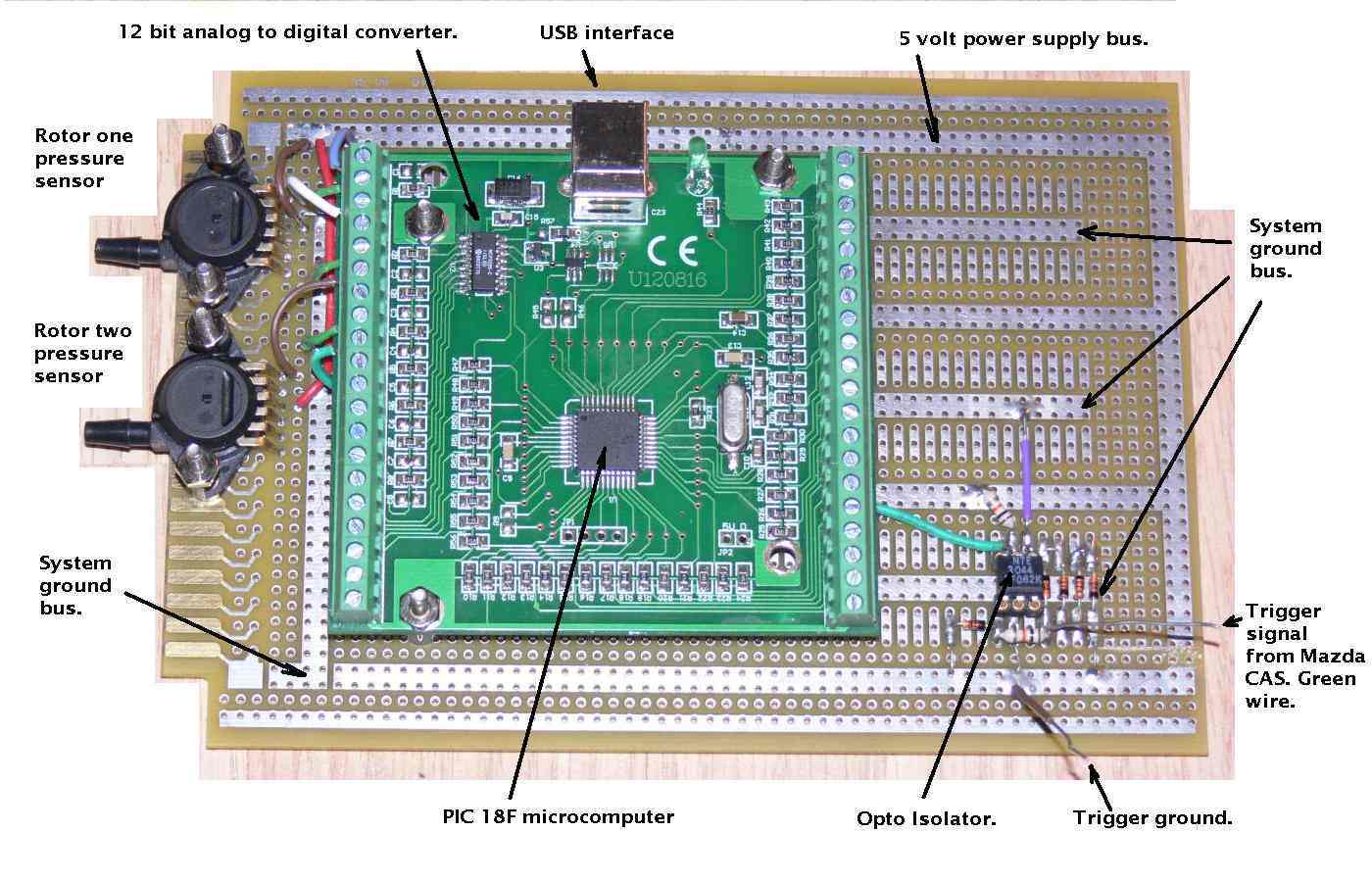
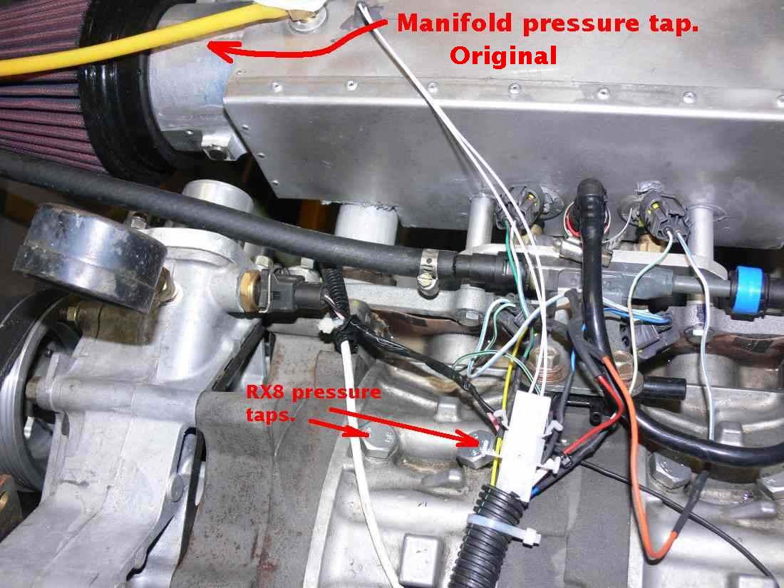
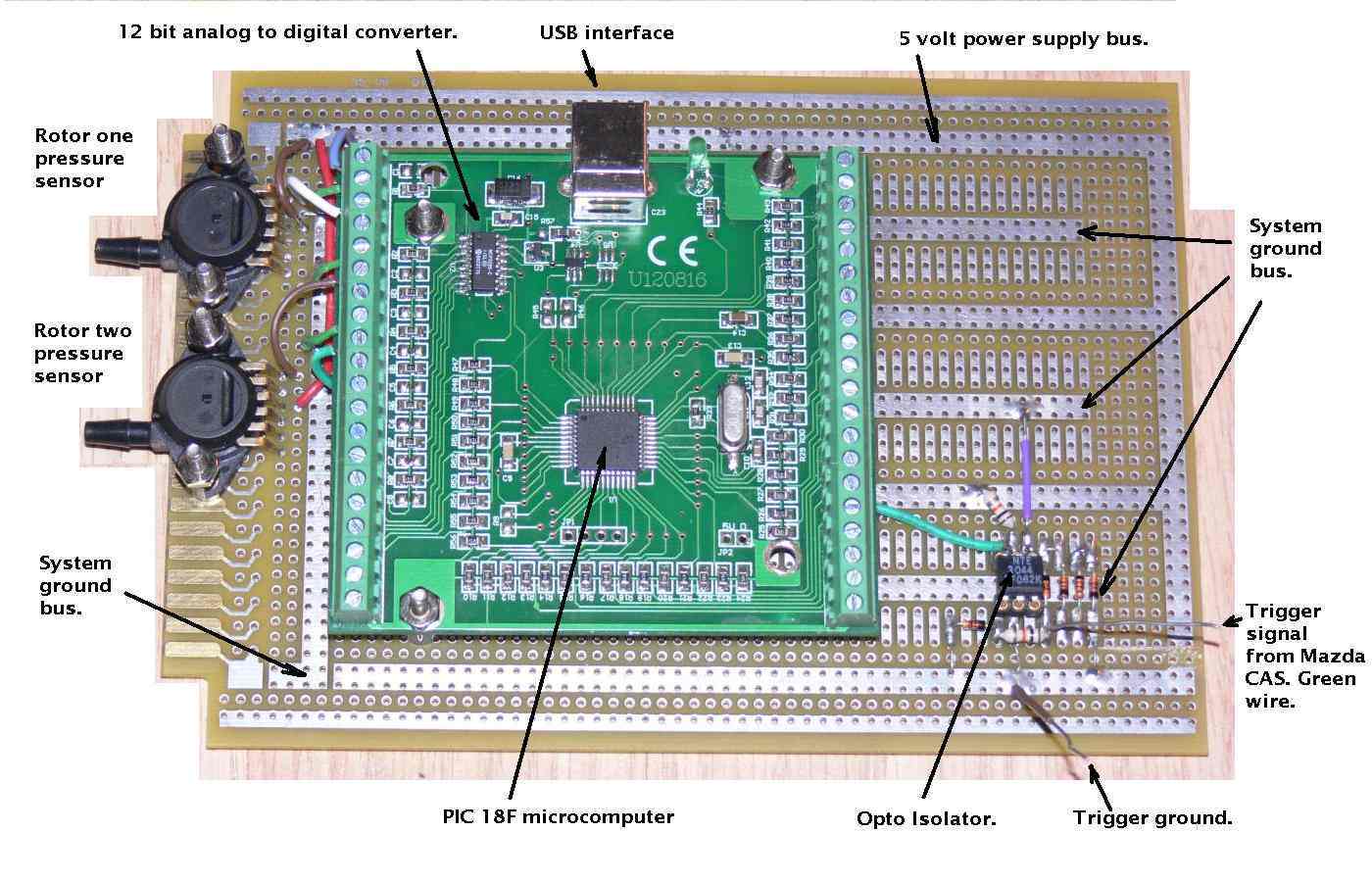
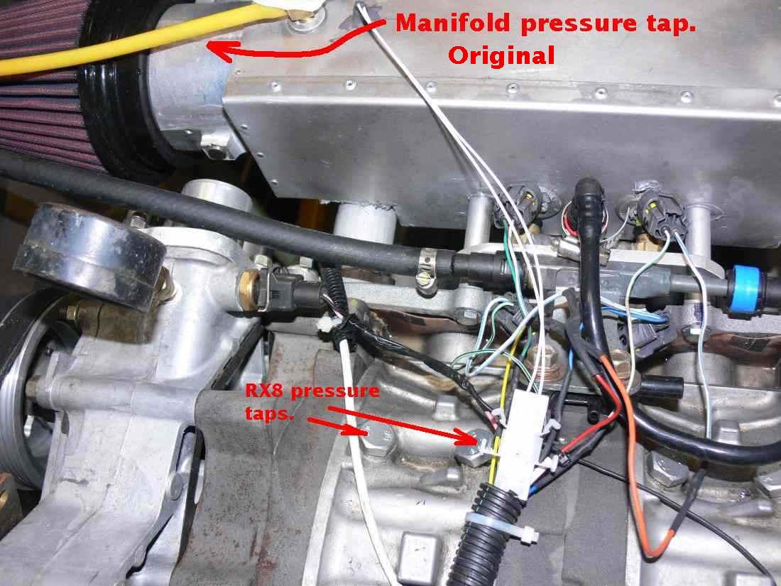
That is the reason I propose measuring the pressure here.
This is the apex seal oiling hole. Most people don't use it.
They mix the oil with the fuel 1 oz per gallon.
So far this seems to be working best.
Tracy does not tell me when (relative to e-shaft position) or how
often he takes a 2 micro second snap shot of the pressure.
The 555 system will automatically average things out
as it is looking at this hole all the time. It takes
a millisecond for the pressure sensor to respond to changes.
The data was taken 1000 times a second with the same pressure
sensor Tracy's uses.
Paul Lamar
I wonder if the data would look different if the sensors were located
directly adjacent to the taps instead of connected through tubes several
feet long. It appears the engine had little or no load as the MAP was
around 13 inches. Larger variations in pressure would be expected at
higher power settings. I notice the two rotors has slightly different
waveforms. even allowing for only 9 samples per cycle. Were the tubes
different lengths? When you get the engine running, it would be nice to
see if the length of the tubing alters the data.
I would be surprised if Tracy did not average the output of the sensors
with low pass filters before using the information internally.
Victor
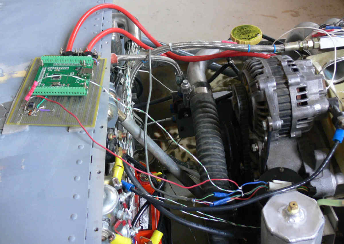
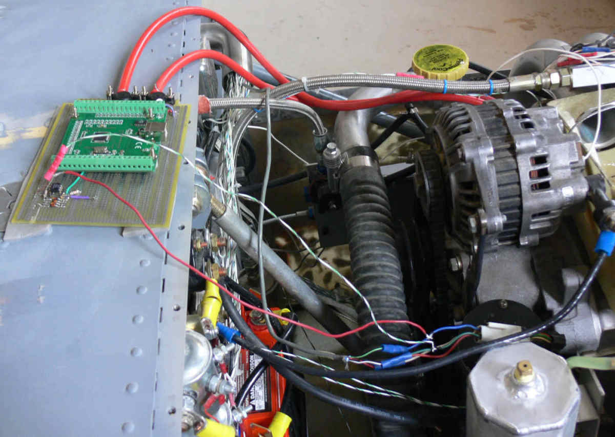
That is easy to try. I can get the sensors within 6 inches of the
RX8 pressure taps. The hoses were about 18" to 2 feet on the
first go around. The RX8 test engine rotor housing taps can
be teed together.
I have got to get these RX8 coils working first.
Did Tracy averaged the output of the sensors? I would not be surprised.
the EC1 had a LM339 quad op amp close by each sensor. Good call Victor.
I have not looked at an EC2 as it is harder to second guess as it
is surface mount.
Paul Lamar
--
The Rotary Engine NewsLetter. Powered by Linux.
ACRE NL web site.
http://www.rotaryeng.net
Youtube key word PaulLamar2
Copyright 1998-2010 All world wide rights reserved.