Roger,
Many piston engines are not well balanced, it is a matter of the design.
Horizontally opposed engines are inherently balanced. As long as the
components are close, the engine is smooth running. Inline six's and the
derivative V-12's are also well balanced.
Inline fours suffer from a secondary shaking force. When the engine
is at TDC
two pistons are at TDC and two are at BDC. The engine has a center
of gravity.
Now rotate the engine 90*. The center of gravity has changed. The
explanation
is that as the crank rotates, the conn rod and piston not only move
down the
bore, but the rod also moves to the side. Pythagorean theorm states
Asq'd +
Bsq'd = Csq'd. Now if the C is the rod length and B is 1/2 the stoke
the math
will tell you the effective rod length at 90*. The piston will be
lower in the
bore the 1/2 the stroke. Thus the center of gravity wants to move
the engine
to keep the Cg in the same spot.
V6 engines are a nasty mess of vibrations with rocking couples in
the mix.
They want to rock forward and back, and then side to side depending
on where
in the rotation the rod throws are. Early Buick V6's had very soft
engine
mounts to try to isolate the vibrations.
The rotor moving in the housing is sort of like an inline 6 crank.
When two
throws are at TDC the other four are at 120* and 240*. The two low
ones have a
higher mass combined, but that is closer to the rotational center.
Now the
rotor when at TDC has two apex seals that are vertically one over
the other.
If you measure from a line between them and another horizontally to the
e-shaft center line and measure the distance it is less the the
rotor radius.
Thus you have a higher mass at a shorter radius. There is still some
imbalance
that the balance weights take care of. Many piston engines also have
balance
weights. Sm block Fords, 400 Chev, BB Chevs to mention a few.
Dale Davies
Like an inline six? Hardly.
"When two throws are at TDC the other four are at 120* and 240*."
What do you mean by a "throw" ?
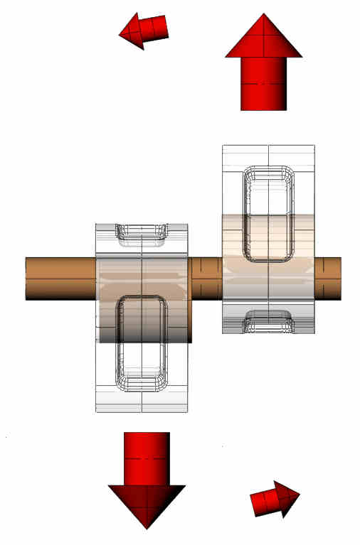
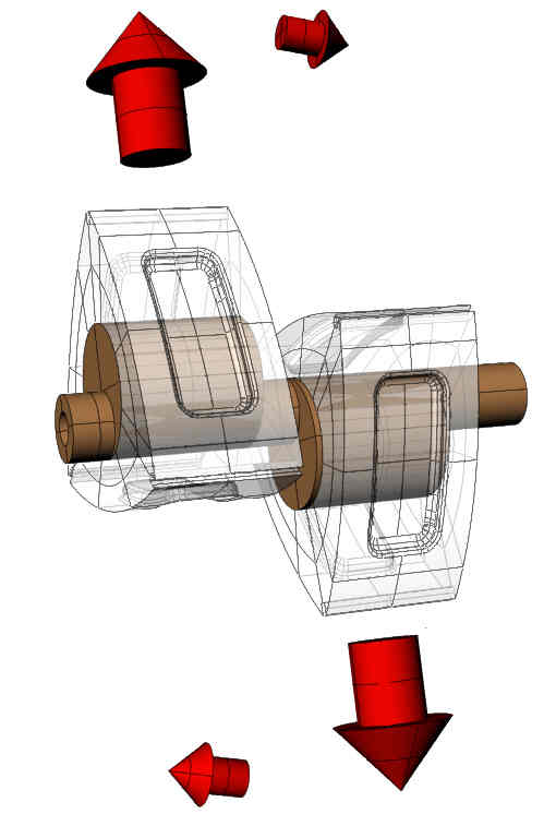
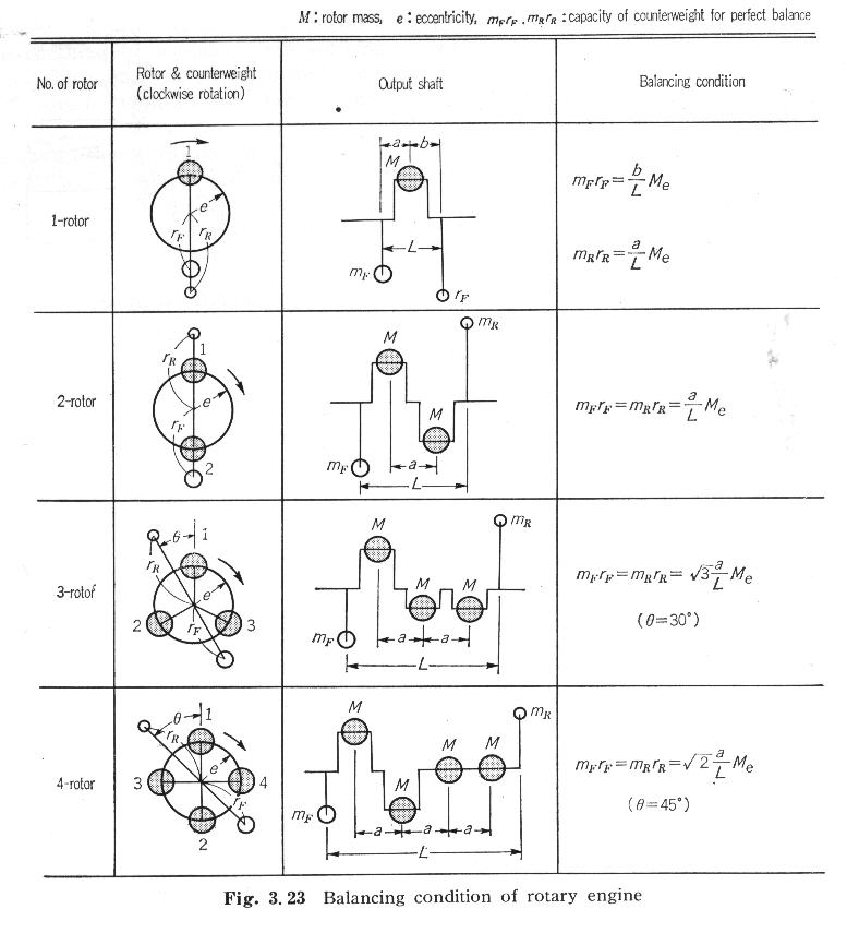
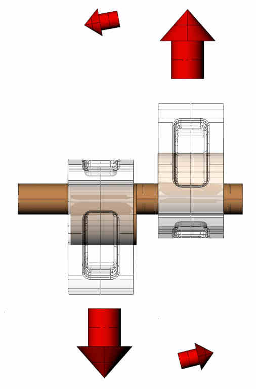
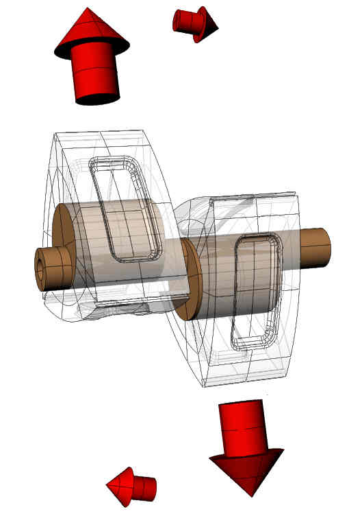
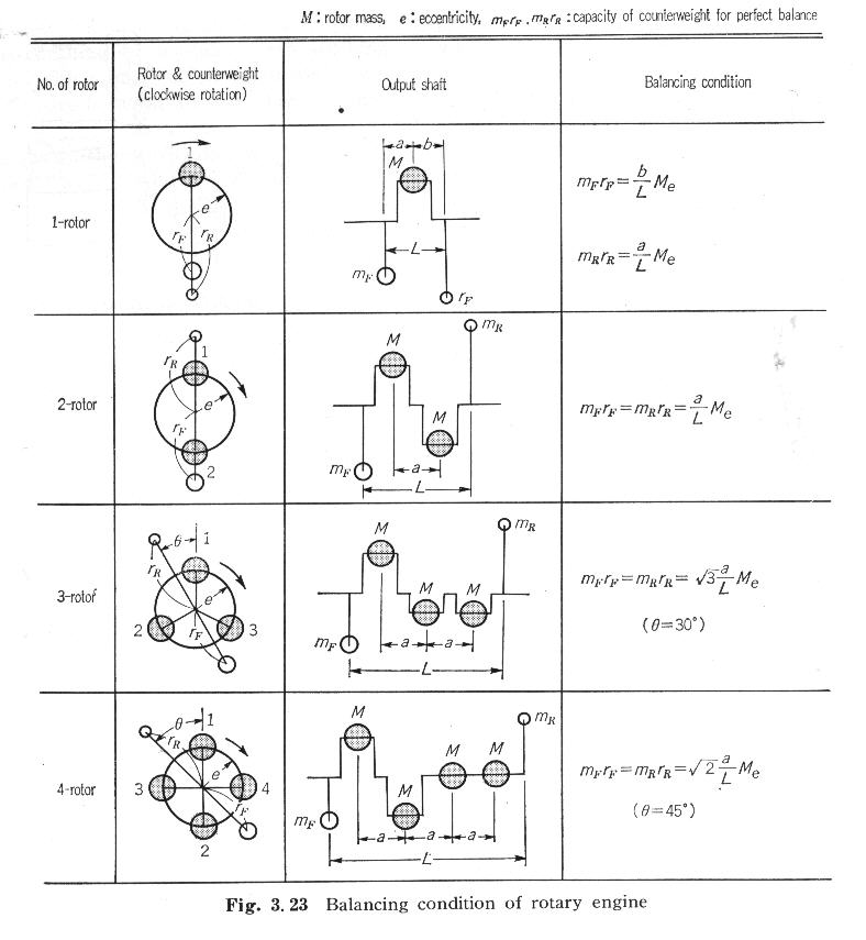
The two rotor has two eccentric 180 degrees out. The two rotors
exactly statically balance each other. Since there is an offset between
them they are dynamically out of balance. This is completely
canceled by the
counter weights. As you add more rotors the counter weights get
smaller and smaller.
Piston engine balance is a complex subject.
The rotary is very simple by comparison.
I recommend For those of you with an engineering degree or
equivalent Taylor's
series of books is the best there is. The bible of engine design.
The Internal Combustion Engine in Theory and Practice.
Volume 2: Combustion, Fuels, Materials, Design. Revised. Charles
Fayette Taylor. The MIT Press Cambridge Massachusetts, and London
England.
Engine Balance Chapter 8 page 240.
When I was at the Mazda factory the vibration test was a glass of
wine sitting
on the top of the engine when running on the dyno. No disturbance.
All engines coming off the assemble line were run on dynos.
Perry Mick's rotary is bolted solidly in his Long Ez airframe for
the last 16 years or so. No rubber bushings. One can hardly
feel the engine running.
Paul Lamar
Dear Paul,
I would like to reduce the weight of my rotors by milling slightly the
sides, however after such operation I would need to balance the. Since I
am in Malta, which a small island next to Italy, it is would be very
expensive to ship them to the states and backwards. Can you please
advise how I can balance them ?
I was told that I should be able to balance them on a lathe, as long I
have the right "bob weights". Are you aware of such process, if yes can
you please guide me how to do it.
P.S. I have access to a range of top end machinist on the island.
regards
Roderick
from the tiny Island of Malta
It is very difficult to get the counter weights right.
It is a bit easier with a 3D program like Rhino or SW as Rhino
will calculate the volume and CG of an object. First
you will have to make accurate 3D drawings of the counter
weights.
From knowing the density of the material you will then know
the weight.
Then you can use these formula to calculate the counter
weights. Add or remove material in the dwgs and start over.
You will also have to make some measurements on the position
of the counter weight's CG position relative to the center of
the engine.
It takes longer to describe the process than doing it.
I don't know how to do it with just a lathe.
I think you would have better luck with a tire dynamic
balancer.
I also think it is not worth the trouble to lighten the
rotors by just that much.
Paul Lamar
--
The Rotary Engine NewsLetter. Powered by Linux.
ACRE NL web site.
http://www.rotaryeng.net
Youtube key word PaulLamar2
Copyright 1998-2010 All world wide rights reserved.