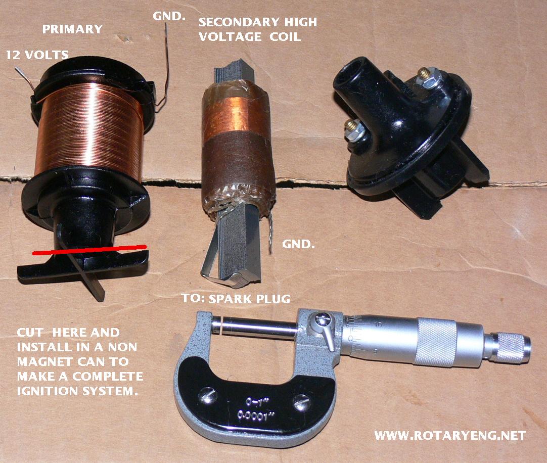
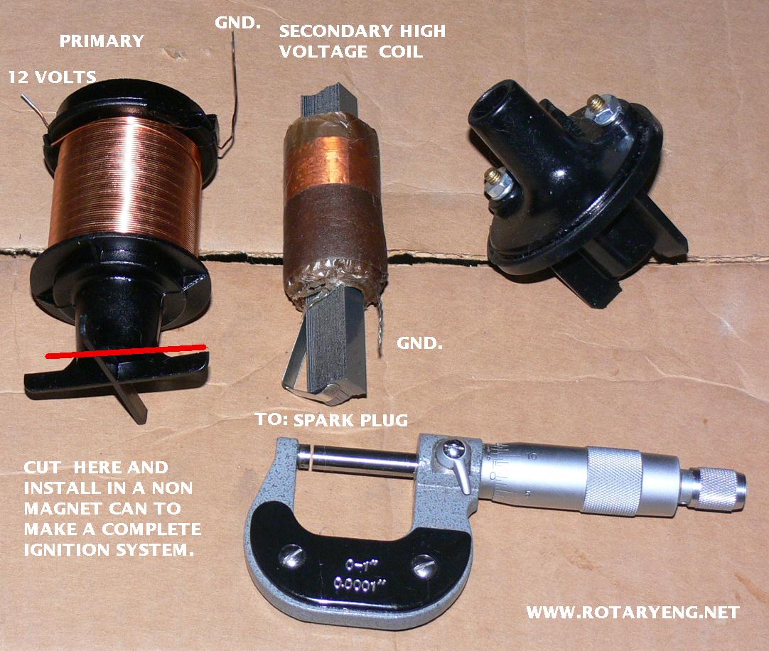
I was wondering how MSD managed to get a complete multi spark ignition
system in just the coil.
"The history of the capacitor discharge ignition system can be traced
back to the 1890's when it is believed that Nikola Tesla was the first
to propose such an ignition system. In United States patent #609250
first filed February 17, 1897."
I was fascinated by the new MSD coil that combines a multi-strike
capacitor
discharge system in the same package as the inductance coil.
Where does the 500 volts come from to charge the capacitor?
Normally a very expensive switching power supply is required.
How do you squeeze a large 1 mfd, 500 volt cap into such a small coil
package?
Can anybody figure this out for me?
Paul Lamar
The documentation does not indicate a CD system, only a multi-strike
system.
A transformer works by having on one side (primary) a fixed coil thru
which is passed a varying current create a magnetic field which varies
according to the rate of change of the current. The other side
(secondary) contains a fixed coil residing within the varying magnetic
field created by the primary current, into which is induced a voltage
proportional to the rate of change of the magnetic field. When the
points make and current begins to flow in the primary, a surge is
induced into the secondary. The theoretical infinitely short duration of
the increase of current is stretched by the inductance of the coil,
which inductance is the product of several factors including the ferrous
mass of the transformer core.
An efficient transformer requires more
mass for lower frequencies, and less mass for higher frequencies. By
selecting materials for a high-frequency transformer, the core will
magnetically saturate very quickly, will have a low inductance, and will
therefore allow the input current and therefore the intensity of the
field to rise more quickly. Thus a spark can be produced when current
begins to flow, and again when it ends, for it is the change in the
magnetic flux, whether increasing or decreasing, that induces voltage
into the secondary.
Another way to multi-spark an inductive system is to use a semiconductor
bridge to reverse the current flow in the primary to amplify the
"ringing" which occurs during the spark event. By alternating the
current direction in the primary at the resonant frequency of the coil
(several times per millisecond) the secondary voltage would increase
dramatically and would spark on each reversal.
Coils designed for multi-spark have a lower ferrous mass and lower
primary resistance. The primary resistance of these MSD coils appears
to be about one-third that of the D-580. The ferrous mass appears much
less than the 580. I am sure their engineers are much cleverer than I,
and could have used some other method to achieve the multi-spark. I
strongly suspect it is inductive and not capacitive energy they are
releasing.
Victor
I am counting on you Victor to think out of the box.
Hint: supposed we tapped off the secondary winding for the 500 Volts
to charge a capacitor?
Paul Lamar
Transformers only transfer energy while the magnetic field is changing,
and with fixed coils that means only while the current in the excited
winding is changing. The voltages produced are a function of the rate of
flux change, impedance of the coils, and load. It is inherent that if we
use the transformer to first charge the capacitor and then to discharge
and create spark, we have two transformer operations instead of one and
doubled the losses and therefore doubled the heat wasted into the core.
Certainly it is possible to conceive a system of using the same
transformer (coil) to store energy into a capacitor and then discharge
it to create the spark, but the devil is certainly in the details -
performing this task multiple times within one millisecond would require
wizardry an order of magnitude beyond my imagination. The coil itself
would be a quantum leap, the electronics much less so.
We are constrained by the characteristics of the available coils. The
coils for CD systems were designed for high voltage power supplies, and
the resistances are too high for primary operation at 12 volts. The
coils for 12 volt primary operation have too much iron for optimum CD
operation.
The folks at MSD Ignition have apparently put a low-resistance primary
winding around a low-iron core which allows highspeed switching to
create multiple sparks.
The MSD coil has a spark duration of 1.2 milliseconds, or 45 degrees of
e-shaft rotation at 6000rpm. I am not sure how much that can be improved.
Victor
Thank you Victor. Now we are on to something. IMHO you are
the best man for the job.
I figure we can use the the 500 volt tap to charge the
cap once the coil fires once in the inductive mode and
then follow up with one or more CD mode sparks. We have
plenty of time to do that at medium RPM with the new existing
fixed 5 ms dwell time coil on plug. If the cap does not
fit in the package an external cap could be used.
I have an old coil that can be used to make a prototype.
Not optimum but can be used to check the concept.
I'll have to disagree with you on old point ignition coils.
They do indeed work with CD as far back as 1960. Maybe
not optimum but the engines ran well. The coil was merely used
as a pulse transformer.
Paul Lamar
--
The Rotary Engine NewsLetter. Powered by Linux.
ACRE NL web site.
http://www.rotaryeng.net
Youtube key word PaulLamar2
Copyright 1998-2010 All world wide rights reserved.