I was reading Tracy's EC2Ainstallation guide pdf
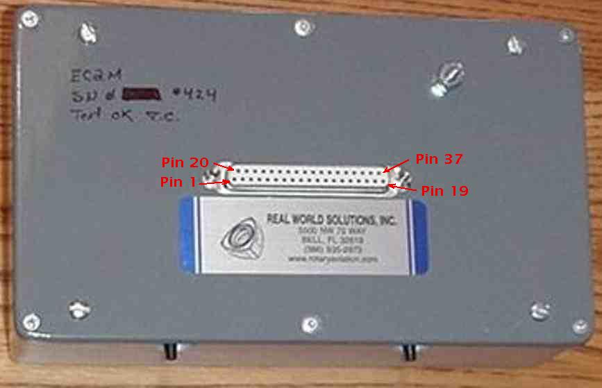
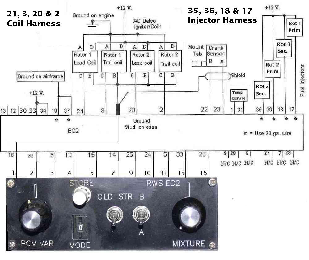
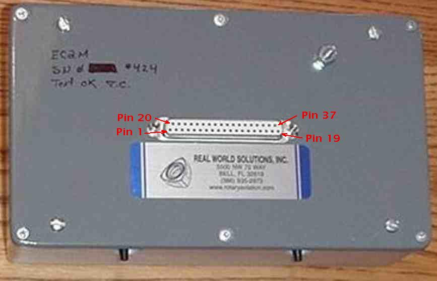
and ran across this illustration of the back side of
a DB37 male connector on page 20 and on page 25 of the
EC2 manual. Then I checked the position of pin
1 on the female mating connector on top of the EC2.
Opps!!! Something did not look right.
Pin 1 was actually on the left on the EC2 and it was on
the right in the illustration. In any even I changed the
illustration and here is the corrected version.
Might seem like a minor point to us old sparkies but
a newbe might be more confused than he is already :)
Paul Lamar
Be VERY sure you are correct about this.Literally hundreds have
been built according to these instructions and no one has had a reversed
wiring problem. Note which side of the connector is referenced in
the drawing.
Tracy
That is not what I am saying. Both will wire correctly.
My point is the illustration in the EC2 manual is disorienting.
I have looked at the EC2 PC board and the ground pins 19 & 37
are on the right looking down on the EC.
My corrected illustration also has the ground pins 19 & 37 on the
right when the mating male connector is plugged in and you are
looking down on top of the EC. If you rotate your illustration
180 degrees to orient it the same as the connector on the EC it would
be clearer. That is what I did and re wrote the numbers so they
are right side up.
Am I wrong about 19 & 37 being on the right side of the connector
looking down on the EC2?
IMHO it would help if you labeled the pin numbers on the top
of the EC2.
Paul Lamar
Without looking, I was under the impression that the illustration
showed the mirror image or the other connector. I am not sure
which is illustrated, but in would be on one side of the
connection and the other of the connector, thus placing the number
one pin, et al, on one side looking at its "front" and on the
other looking at its back. Made sense to me at the time......
Chris Houston
The male D-sub min connector will only mate with the female
D-sub min one way.
Here are both illustrations. Which do you prefer?
Paul Lamar
I see what you're saying but don't understand why you would be
looking at the EC2 while wiring the connector. Wire the connector
according to the drawing ( either one ) and you don't need to ever
look at the numbers on the EC2. I would think dividing your
attention between the two would only confuse builders.
Tracy
Well I am taking it a step beyond just wiring the connector.
I want to make it intuitively clear exactly what is going on
and what goes where.
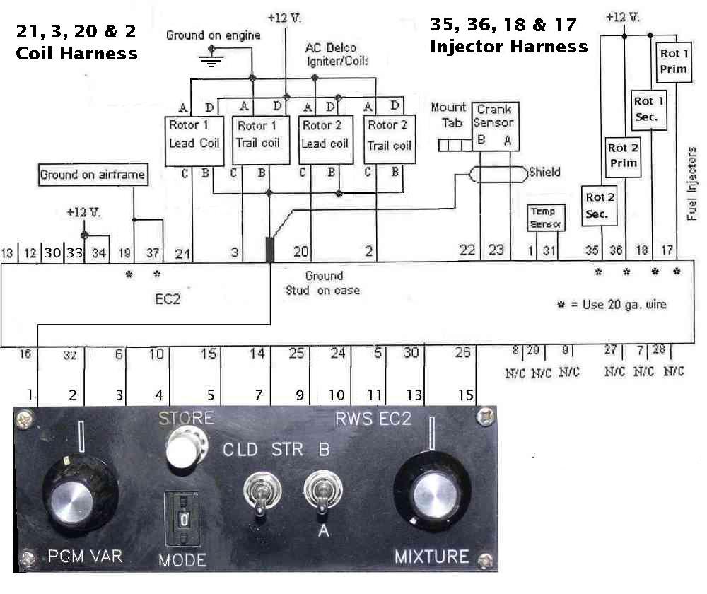
I am organizing things in separate wiring harnesses according to function.
This makes it easier to understand and deal with as each harness
can be done one at a time. One simple step at a time.
I have broken the job down to 5 harnesses. Starter alternator
harness, Sensor harness, Injector harness, Coil harness and PCM
harness. Since it is hard to get wires in more than about 4 or five
colors this makes the job much easier. I have located some 12 wire
color coded vinyl jacket cable for the PCM harness.
Since I am using the the terminal strip break outs for the D sub
min connectors on the EC2 and PCM It cuts the job down to one or
two days for the whole thing. It is also a lot neater and easier to
trouble shoot and fix wiring mistakes.
I will reveal the new invention next week when the prototype
is done :)
I have two buses on the top of the engine to feed
power and ground to the coils and power to the injectors.
The test switches are not implemented on this go around.
Here is a picture. The goal is a visual inspection capability.
BTW I bought Mike's RV4 so I will probably rewire that too.
I am also working on a heat sink for the RX8 coils.
Do you have a source for RX8 coil connectors?
I need at least 8.
Paul Lamar
Seems to me like right brain / left brain. Illustration just
rotated 180*. As long as it makes sense and the builder is
watching the terminal numbers.
Dale Davies
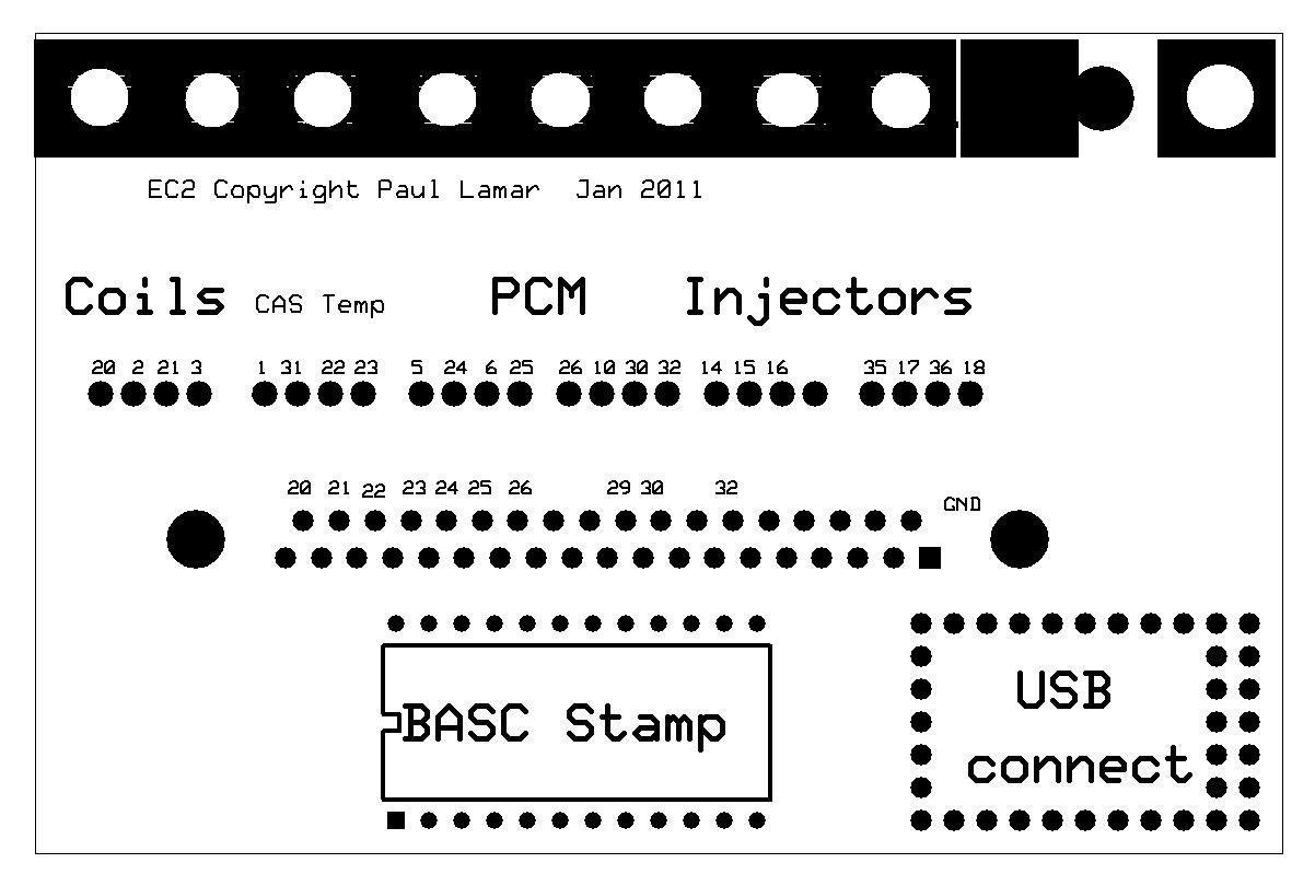
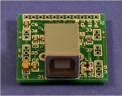
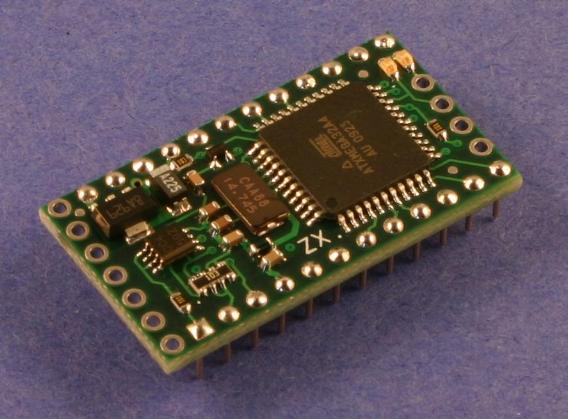
Here is what it is going to look like. The break out board is going
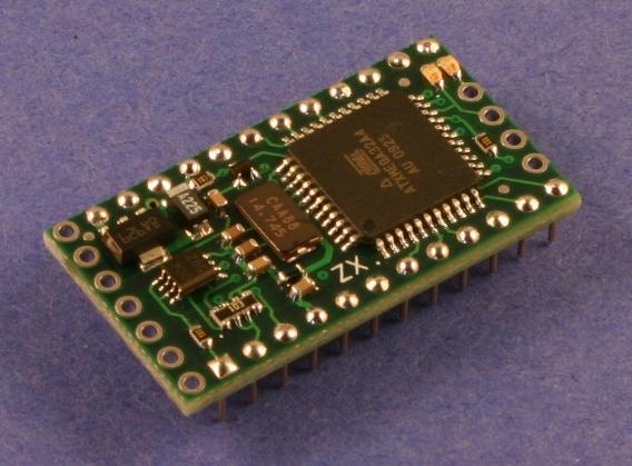
to group the 37 pin D sub min pins into harnesses. There will be a small
computer on the board that will monitor all the CAS, injection and ignition
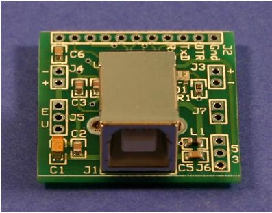
pulses and their width and send the data to a PC through a USB
interfaces to be recorded on the hard disk. This will give a
complete black box type record of the engine performance for the
entire flight. Including fuel used and RPM. This wil be an option to
keep the cost down for the basic break out board.
One glance at the data will determine if anything has failed in the
main computer or the crank angle sensor. Sort of OBD II for aircraft
computers :)
Paul Lamar
The diagnostic ability will be a huge benefit.
Dale Davies
I agree. It should make it easier to tune as well
as all injector pulse widths will be recorded.
If it is running like crap at a particular RPM
you will see why but looking at the pulse width
change. The manifold pressure is pretty much a
function of RPM as the prop is known load.
If I am lucky enough to get an A to D in the BASIC
stamp I can monitor MAP directly.
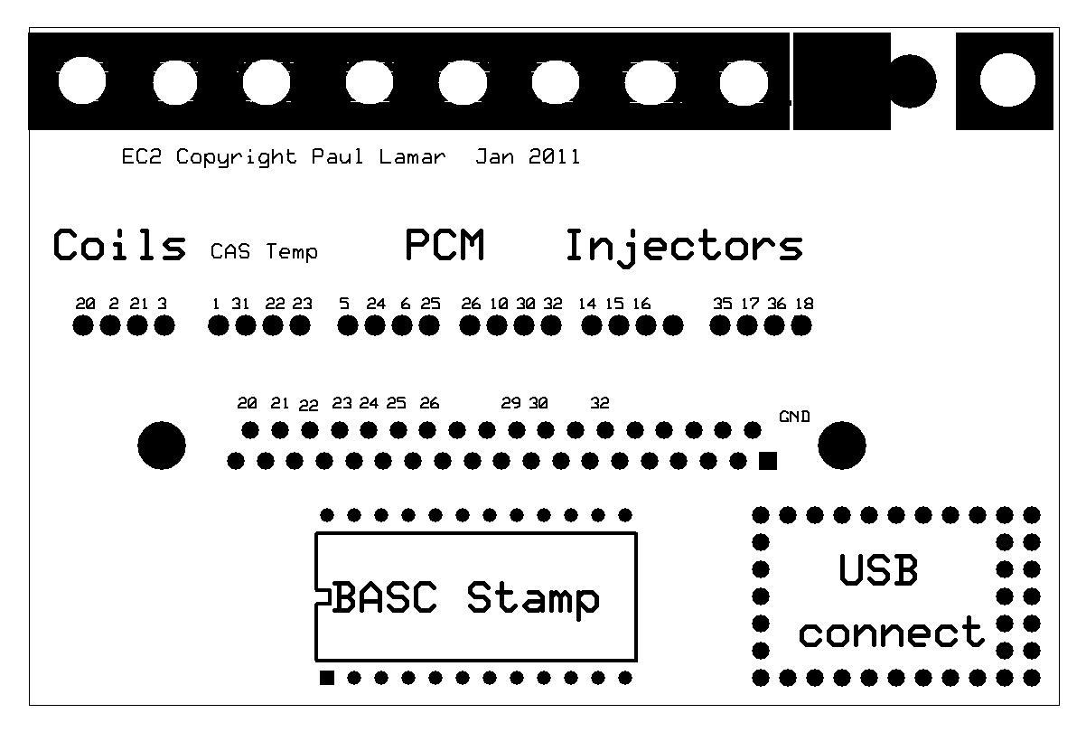
Here is a preliminary sketch. I am still refining
the pc board layout. I have been through about a dozen
iterations so far. I have to get it down to 2.5" by 3.8"
to get a good break on PC boards. When I am done it probably
won't look anything like this.
Paul Lamar
--
The Rotary Engine NewsLetter. Powered by Linux.
ACRE NL web site.
http://www.rotaryeng.net
Youtube key word PaulLamar2
Copyright 1998-2011 All world wide rights reserved.