If you are wiring something and you need to fix something it helps to know
how it works.
I am wiring up an RX8 test engine and EC2 and I found out I had a lot of
EC2 break out PCB board space left over. I then had the bright idea of using
that space to implement OBD II for aircraft EFI systems using a BASIC stamp.
One of the first problems I ran into was how to implement monitoring the
injectors.
Not as simple as it seems.
Here is how the computer controls the injectors.
Injectors are simple solenoids. The top of the solenoid is connected to 12
Volts. When the solenoid is off there is no current flow. That means the
bottom of the solenoid is also 12 volts believe it or not. One of the
strange things about OHM's law.
Tracy uses a transistor connected to the bottom of solenoid. Transistor are
merely switches. The mechanical lever is replaced by a wire with a voltage
on it fed into the transistor to turn it on. When the transistor is off it
is seeing 12 volts from the injector. Now if I feed
12 volts into a computer chip on the BASIC stamp it would blow up lickity
split.
How then do I use another computer (The BASIC stamp) to monitor the injector
pulse width with out taping into Tracy's computer?
The trick is to use a device called an opto isolator and connect that to the
bottom of the injector.
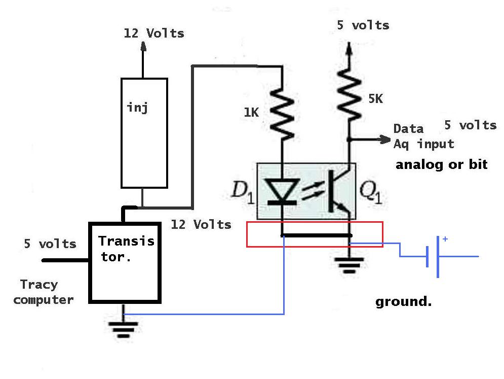
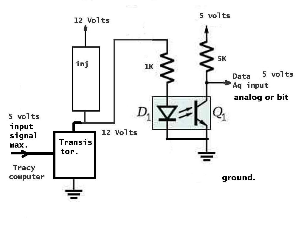
The 12 volt lights the LED in the device and a photo transistor turns on
when it sees the light. When the injector turns on the LED goes out and the
BASIC Stamp sees a negative going injector pulse.
Here is the schematic. I added four of these to the breakout board. One for
each injector.
Questions? Did I explain it well?
Paul Lamar
Hi Paul
The schematic published in reply mail is not correct.
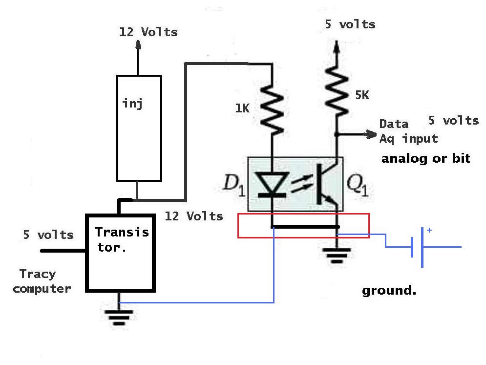
To my knowledge the connection within the red square is not allowed. it
should be like the blue one
if not you lose the galvanic isolation (no metal connection). The secondary
circuit should have it own power supply by means of battery/own separate
trafo.
Regards
Gino De Baerdemaeker
Not true.
The grounds as drawn are correct.
IMHO you are misinterpreting the the 5 volts on the left.
That is the max value of the transistor control voltage.
I should have been more clear.
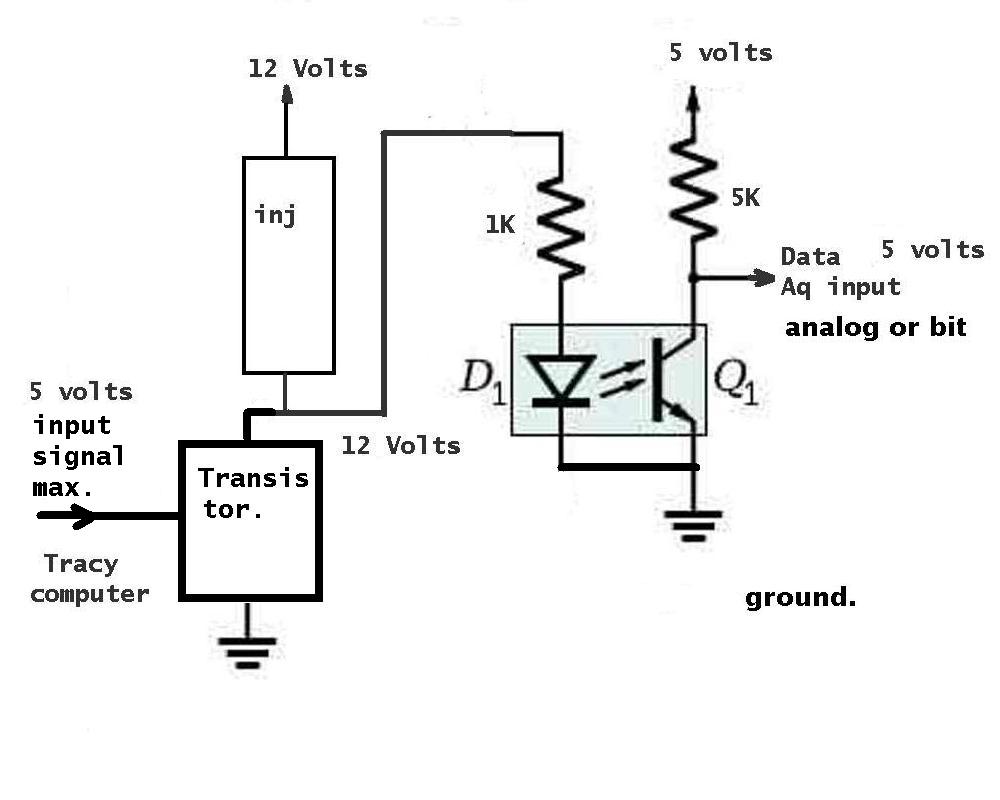
Here is the corrected dwg.
It is called level shifting.
We are not looking for isolation.
The five volts power supply for both computers is derived
from the 12 volts power shown on the schematic.
Paul Lamar
--
The Rotary Engine NewsLetter. Powered by Linux.
ACRE NL web site.
http://www.rotaryeng.net
Youtube key word PaulLamar2
Copyright 1998-2011 All world wide rights reserved.