This was a lot harder than it looks.
There were no specific dimensions from Garrett on exactly
how to install this in an Hitachi compressor AKA 2nd gen Mazda
turbo. They merely say take this to a machinist. Yea sure.
The learning curve was rather steep. The sensor has
a 6 mm .5 mm pitch extremely fine thread.
We at first tried to tig weld the mounting tube in. That
proved to be unworkable as it distorted the threads.
We had to start over with a new threaded tube.
JB Weld is the only practical solution. One must treat
the aluminum with a preparation kit or the epoxy
in JB Weld will not adhere to aluminum that has had a chance
to oxidize or weather in other words.
The rational for this tachometer kit is the centrifugal loads
on the turbine blades are extremely high at over 100,000 RPM.
The loads are in fact proportional to the SQUARE of the RPM.
If the loads are 100% of failure at 100,000 RPM they
will only be 72% at 85,000 RPM. Since we don't have
any real numbers of how long the blades will last at any
given RPM I have decided to limit the RPM to 85,000 for now.
Later on, after we get some real world numbers on what continuous RPM
the blades fail, than maybe we can up the turbo red line.
Many people have failed Mazda 2nd gen turbo turbines and Mistral had gone
through three all by themselves. Unfortunately they did not
record turbo RPM numbers. Nor did anybody else for that matter.
The rotary exhaust temperature being several hundred degrees F higher
than a piston engine does not help. That drastically weakens the metal.
The metal tensile strength goes from 60,000 psi at 1200 F
down to 5,000 psi at 1600 F. BTW That is the root cause of exhaust valve
failure in piston engines. An exhaust valve dropping its head is a
catastrophic failure. That alone makes the rotary ten times more
reliable.
No exhaust valve!!!
If a turbo charger turbine fails it is more like an annoyance as the
parts go out the exhaust. The engine still runs while still generating
considerable HP. No crashes have been attributed to turbo charger
failure.
In a car the turbo never runs flat out for long. Usually just
a few seconds in an all out drag race. The opposite is true for
cruising at high altitude in an aircraft engine hour after hour.
The higher the altitude the lower the back pressure on the turbo
and the higher the turbo RPM.
Paul Lamar
Paul,
I would think that there would be a direct proportion between
the boost pressure (at the time of failure) and the rpm. That is to
say if other parameters are equal; runner size, exhaust diameter/length,
etc... Has any of these failed turbo owners remarked as to how much
boost they were making at the time of the failure (or had they peaked out
just prior to things coming undone?)? IIRCC, turbine tach.s read percentage
of total power and the source is oil pressure, not actual blade count.
rnc
The pressure on the turbine blades plays a minor role.
The boost is generally a function of the turbo RPM but it varies
with the size and detail design of the compressor.
It is the centrifugal load on the blades and high temperatures that
cause them to fly off. These same forces limit the RPM of a turbine,
the rotary engine itself and how fast a car can go around a corner.
The formula is m * V squared divided by the radius.
This is a fundamental LAW of physics not to be trifled
with :) It is not just a good idea. It is the LAW!!! :)
Here is a little demo. Get a small drill motor and clamp it in a vise.
Tie a 6-32 nut on one end of a rubber band.
Chuck the other end in the drill motor. Place a large cardboard box around
the drill motor. Have absolutely nothing in the plane of the drill motor.
Lock the drill motor trigger on with tape before plugging it in. Plug it in
from a safe place out of the plane of the drill motor. 3/4 inch plywood
should be adequate armor.
Paul Lamar
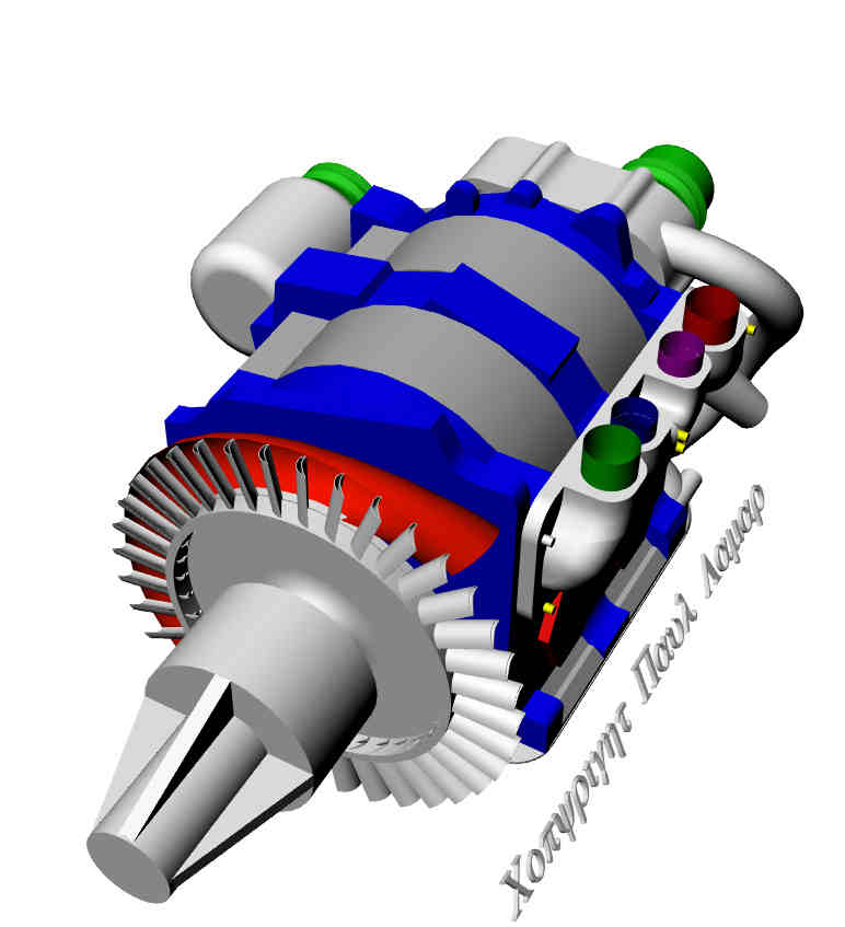
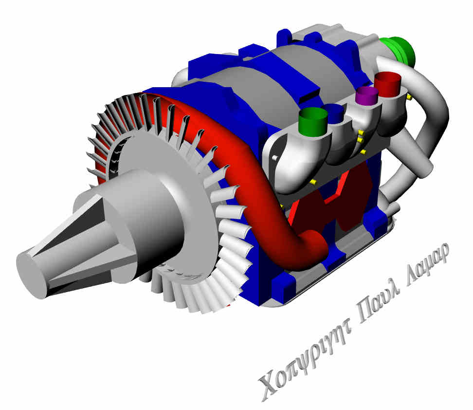
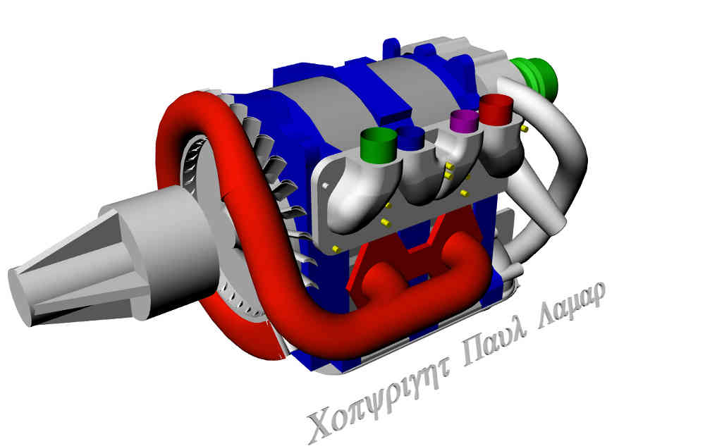
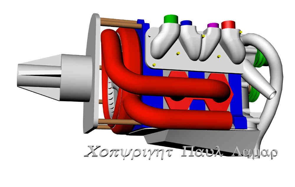
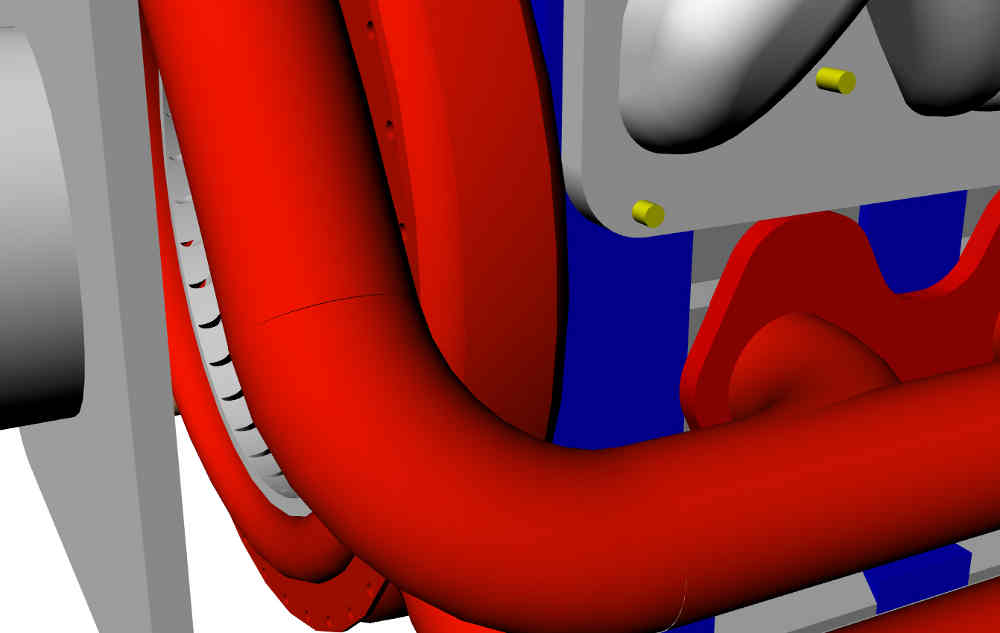
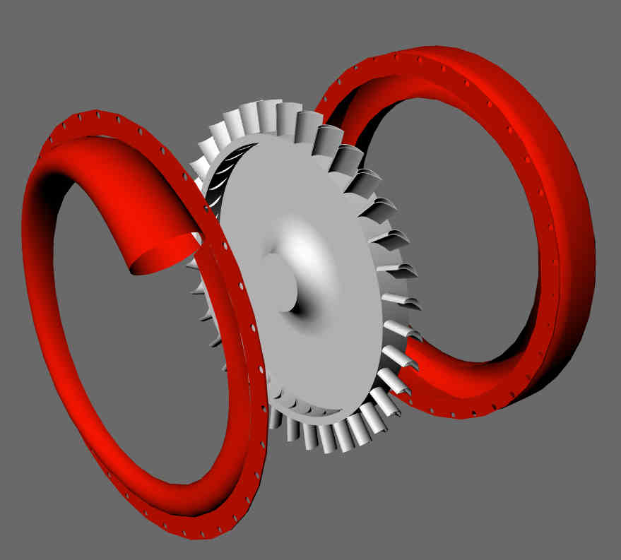
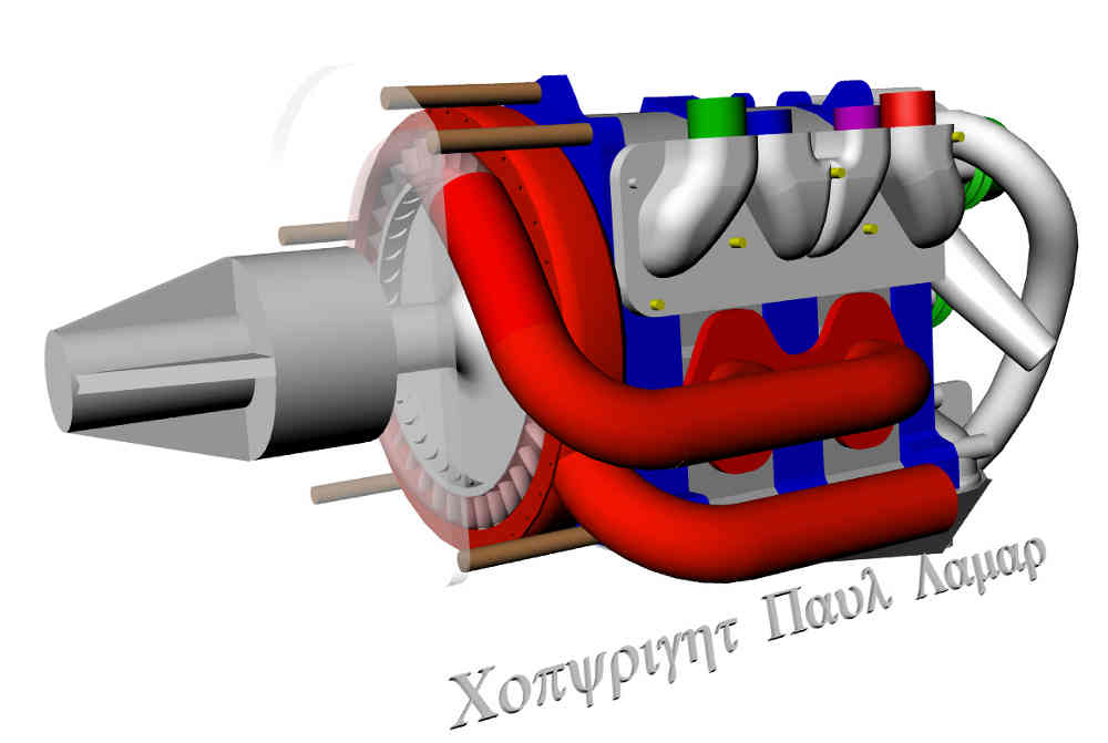
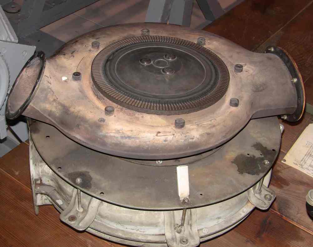
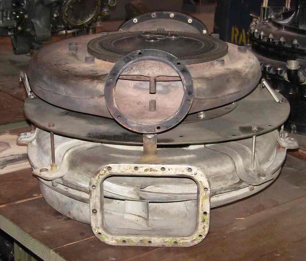
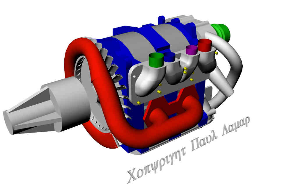
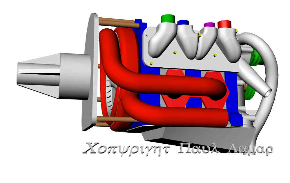
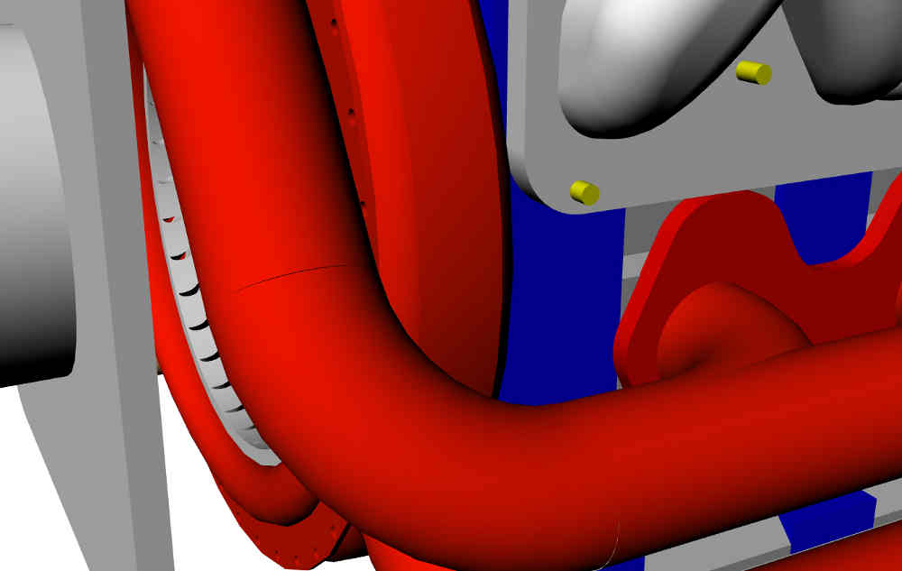
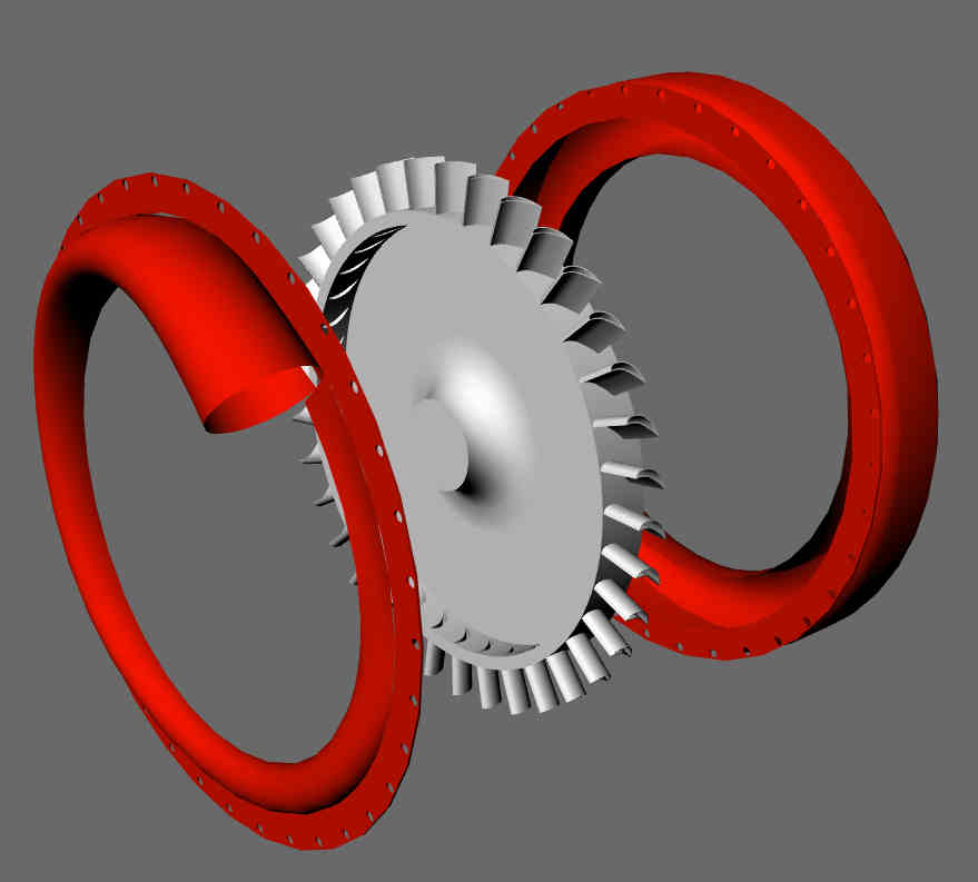
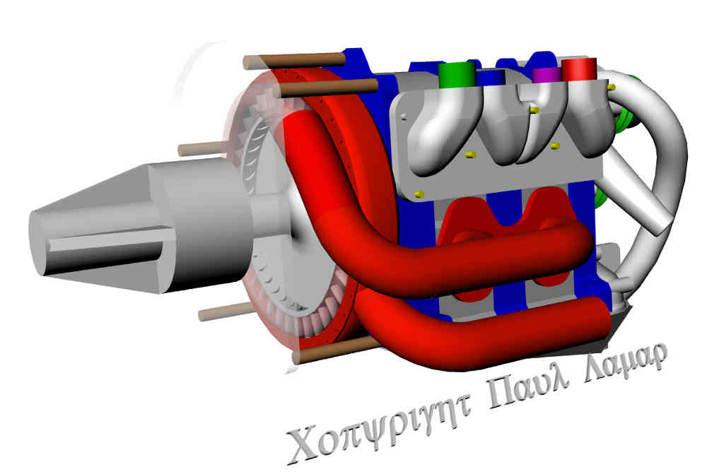
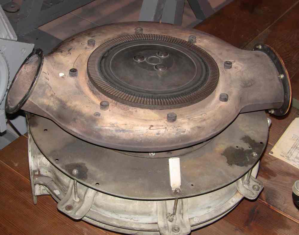
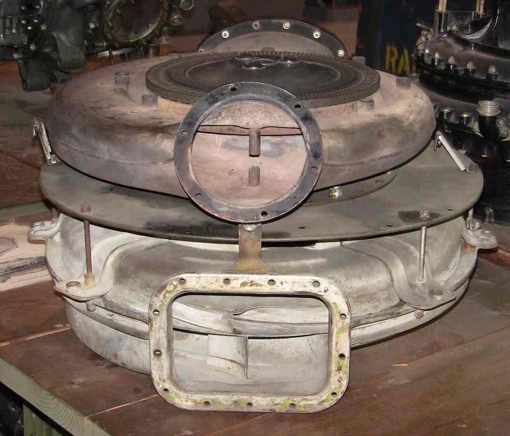
Back before WW II the aircraft turbo manufacturer figured all this stuff out.
Their solution was to use an axial flow turbine to power the compressor instead
of a radial inflow turbine. It was easy to make the blades hollow which reduced
the mass. The secondary effect was to automatically pump cooling air through
the center of the blade. That is the ultimate solution for an aircraft turbo.
Rotational inertia is higher than a radial inflow turbine universally found
on automotive turbocharger but we don't need rapid spool up. The P38, P47 and
the B17 among others all had axial flow turbines on the turbo chargers.
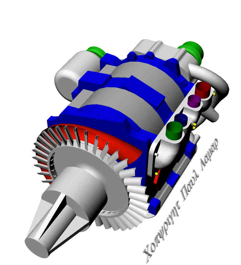
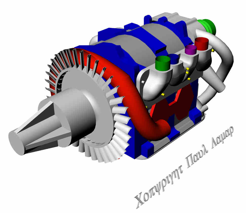
Here are some pictures. BTW it is also a good solution for a hot exhaust turbo
compound rotary.
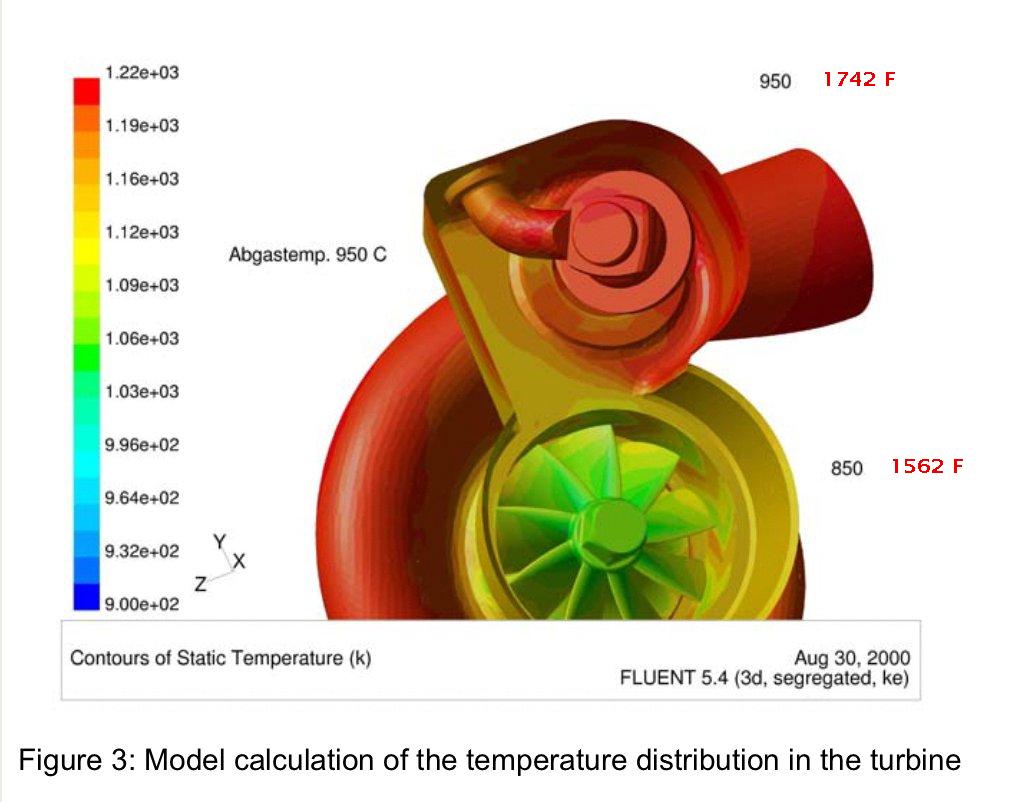
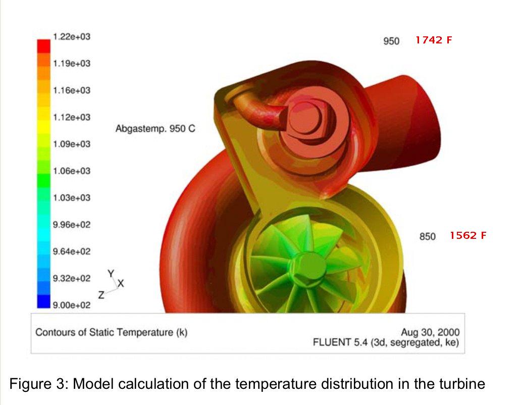
There is another way to improve the 2nd gen turbo situation. Increase the water
and oil flow to the turbo. That will help cool the turbine blades better. See
the attached FEA on a turbo charger temperature distribution. If you increase
the turbo oil flow you must increase the drain back hose size. We went up from
1/2 inch ID to 3/4 inch ID. From .78 square inches to 2.36 square inches. That
we have done on this engine. We will also increase the oil supply side by doing
away with the stock banjo fitting on the front end housings and use a straight
fitting. The stock cooling water supply comes directly from the block after the
water has absorbed heat from cooling the rotor housings. We will change that to
get cooler water on the outlet side of the water pump right after it comes from
the rad.
Every little bit of turbine blade cooling increase helps the tensile strength of
the blades enormously.
Paul Lamar
--
The Rotary Engine NewsLetter. Powered by Linux.
ACRE NL web site.
http://www.rotaryeng.net
Youtube key word PaulLamar2
Copyright 1998-2011 All world wide rights reserved.