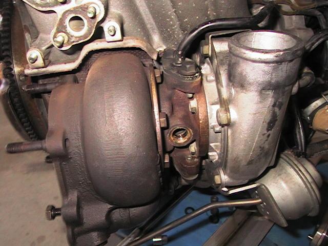
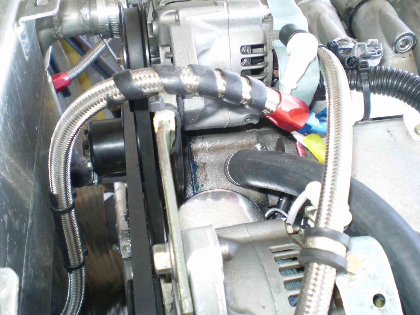
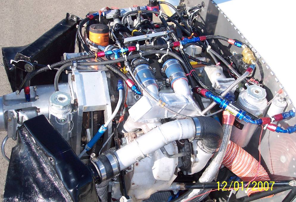
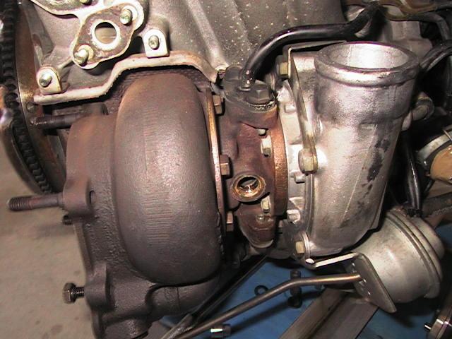
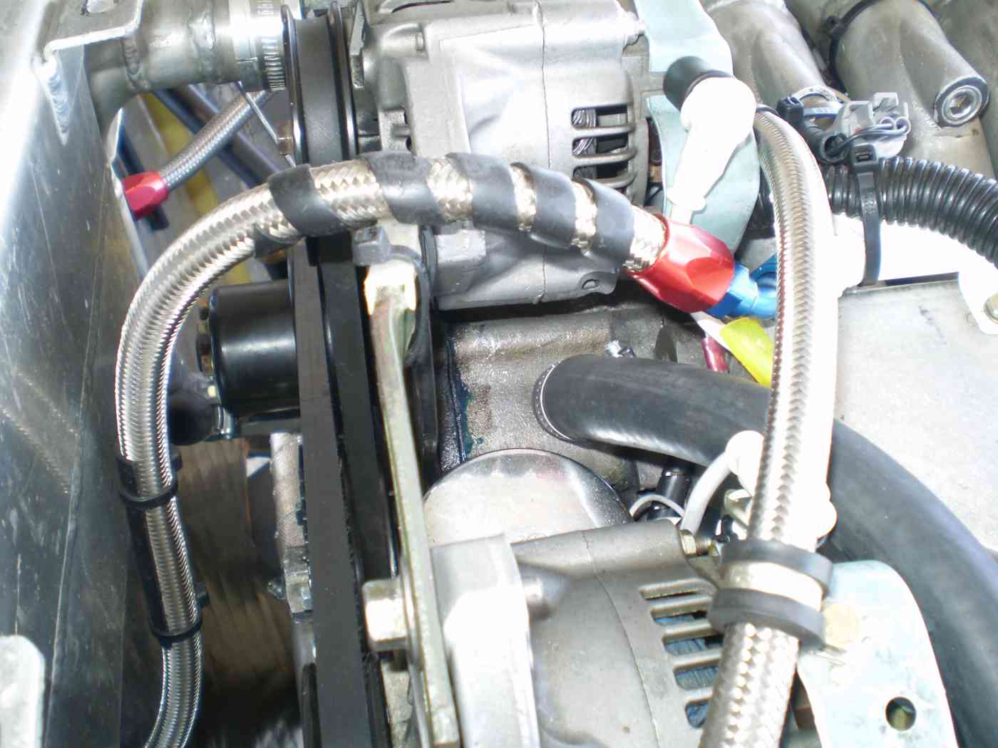
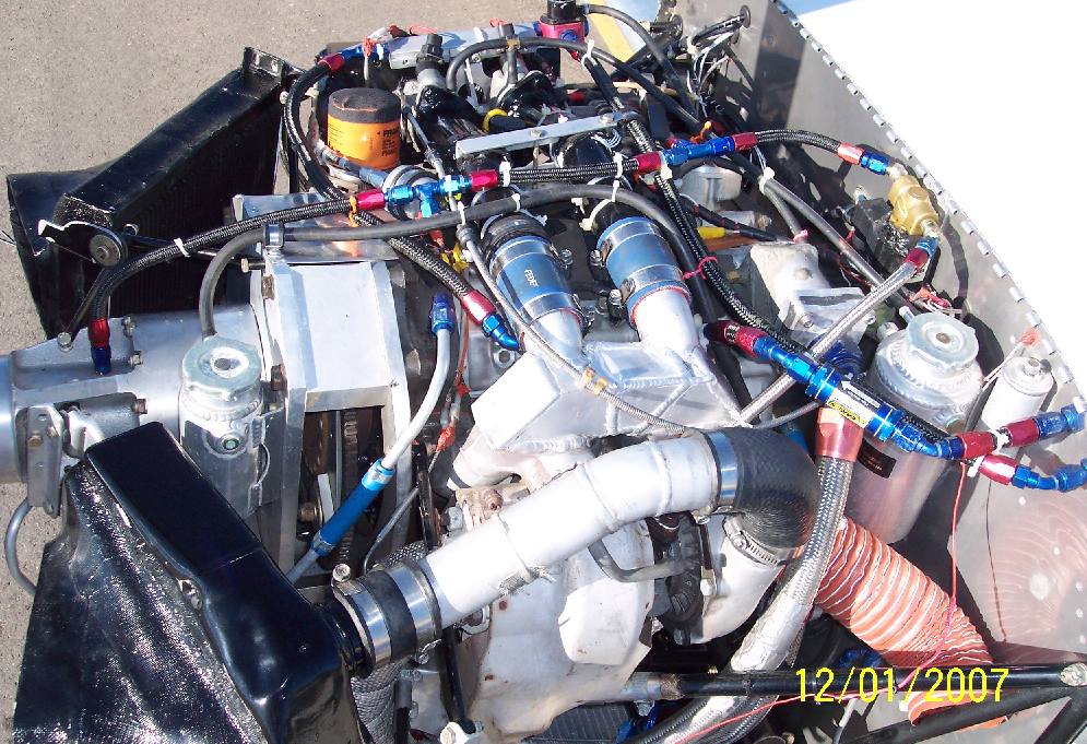
I was in the process of rebuilding the oil supply
and turbo water cooling system on the 2nd gen Mazda turbo
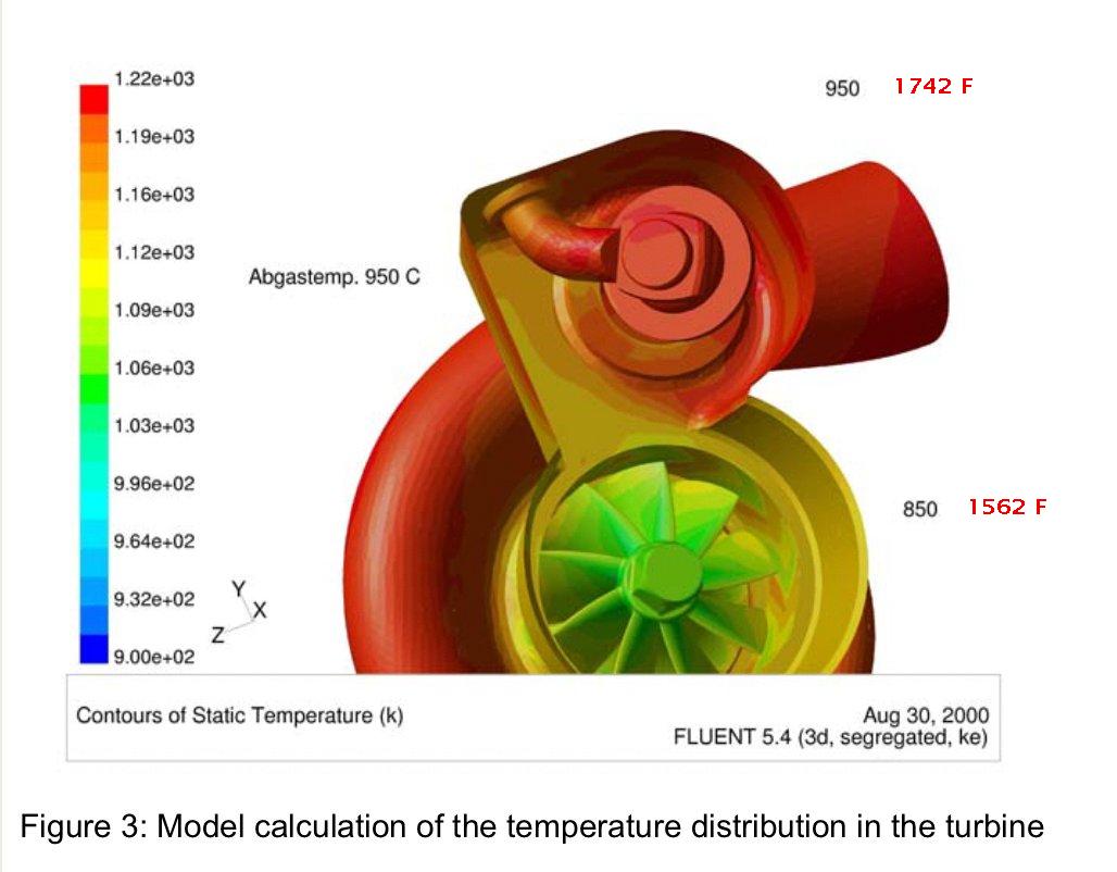
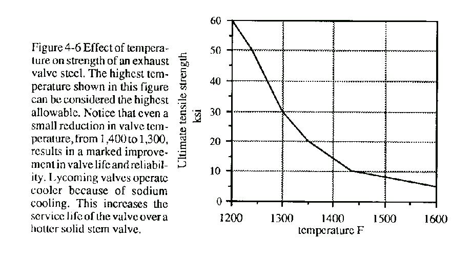
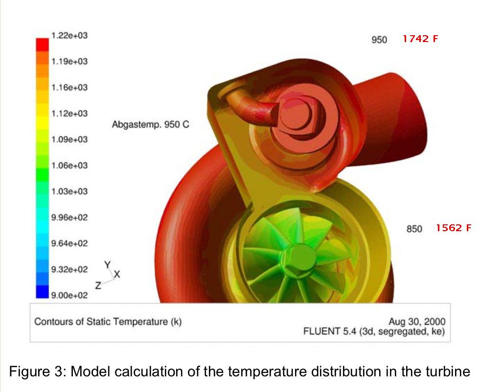
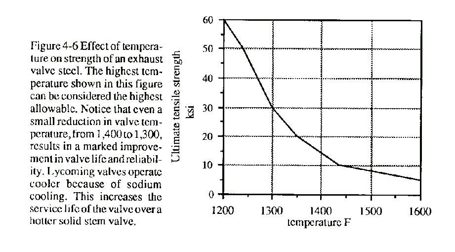
charger. Cooling the turbo shaft has a large effect on the
strength of the turbine blades. See the JPG. The highest stress is
at the root of the blades attached to the shaft. If one can cool
the shaft one can strengthen the joint.
I had redesigned the intake manifold, made casting patterns in
a stereo lithography machine at the local college and had castings
made and machined. We sold out except for the one I saved for the
turbo engine in my KIS cruiser kit. We could not use the original
turbo intake manifold as it was too high for the low KIS cowl. In
fact it was not a good idea to use it cut down as it gave a rather
bad aerodynamic internal shape. Unfortunately, or fortunately
depending on how one looks at it, we lost the turbo cooling water
connection when we redesigned the manifold. I did not think too much
about it until recently when it became necessary to redesign the
cooling system.
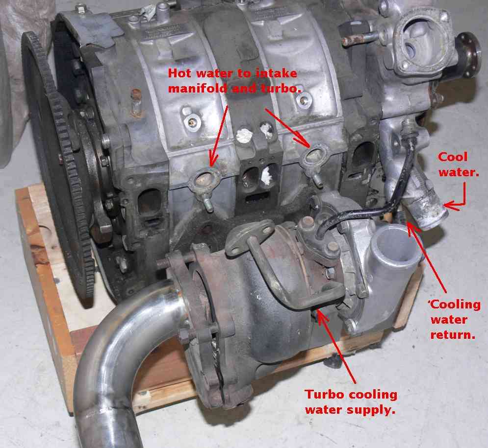
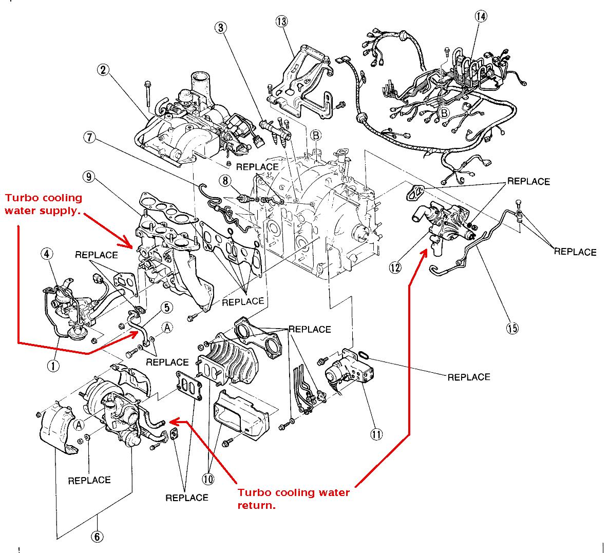
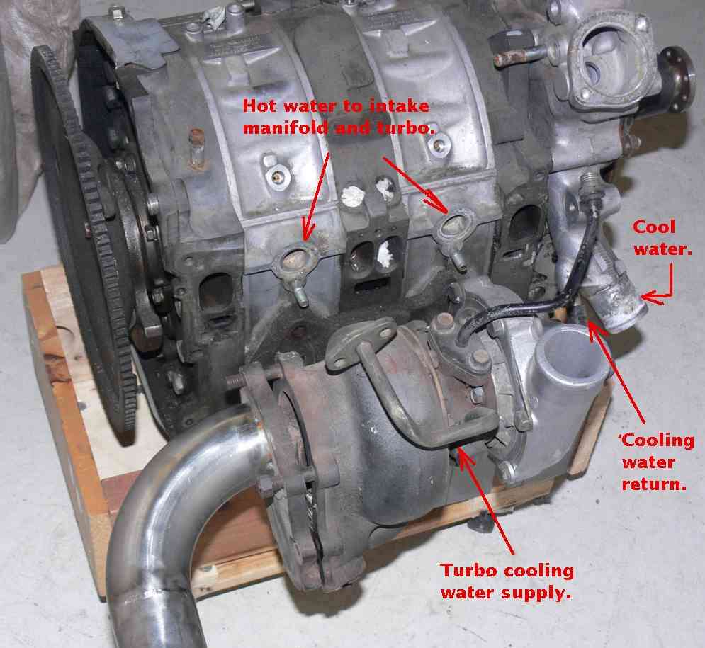
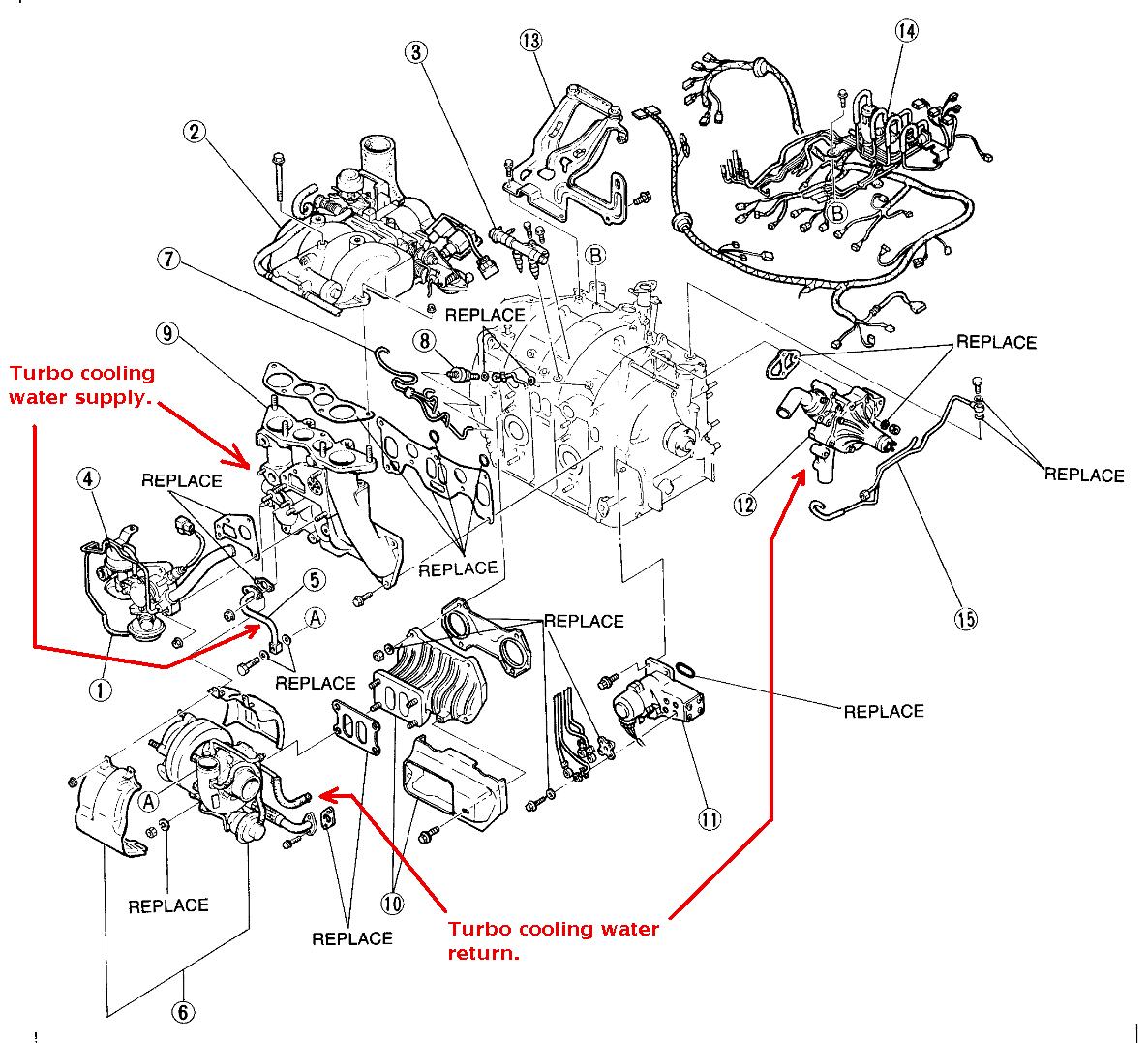
I was stunned to find out the cooling water going to the turbo was
already
heated by the hottest part of the engine. That reduced the cooling
effect on the turbo. The second stunning fact was the turbo
cooling water drain back did not go to the flow of hot water going
into the rad to be cooled yet again as one would think. It short
circuited the rad and flowed back into the input side to the water pump
along with the cool water from the rad!!!
What the heck were the Mazda engineers thinking??? This means the
heat put into the turbo cooling water was now heating the engine
cooling water before it got into the engine and do its job of
cooling the engine???? No wonder it was so hard to cool the turbo
engine as Dave Leonard found out. He had to use a really thick rad.
IMHO It would be much better to send the turbo cooling water to
the rad along with the hot water from the engine. That would increase
the temperature of the rad increasing the heat transfer to the out
side cooling air. That would supply colder water to both the
engine and the turbo.
IMHO this stock turbo cooling system is partially to blame for all
the stock turbo failures we have seen.
What am I missing?
This also has implications for the turbo compound version that
uses a turbo charger.
Paul Lamar
Paul,
There may be a couple of things involved.
1: Maybe they were thinking about after shutdown thermosyphon to
cool the turbo. The shorter distances give less resistance to the
flow helping to increase the flow rate.
2: Having the return going directly into the water pump suction
line will give the highest differential pressure across the turbo
which should help increase the flow through the turbo while running.
I do have to agree the heated water coming out of the engine does not
seem to
make sense. Possibly the temp of the turbo makes the inlet coolant
temp not
important. It does look like the plumbing is short in Mazda's
version. A redesign seems to be in order. For automotive use it is
likely not extremely important but for an engine that will run for
hours at 75% max power, it is looking mandatory.
Dale Davies
1: I guess that is a possibility but that sounds too sophisticated.
2: What do you think of sourcing the cool water out of the outlet
side of the pump and returning to the hot side of the rad?
The water out of the block is close to steam temperature to begin
with. I think steam is coming out of the turbo, as it runs 400 F or
higher around the bearings.
Paul Lamar
Do you think that Mazda was looking at bringing the engine up to
operating temp as quickly as possible utilizing heat from the turbo?
As stated, automotive applications rarely tap sustained power for
more than several seconds.
rog
That is the best reason I have heard so far. Smog is a large issue
for car engines so that would cut emissions.
Thanks rog.
Paul Lamar/
Rog's notion may be part of it all right. For AC use I would
definitely pull
the cool coolant from the water pump outlet and return to the hot
radiator
side to try to lower the turbo temp and get as good a flow through
the turbo
as possible. At that turbo temp, a few degrees cooler in to it may
not be
much
help. A normal running automotive engine ( and most industrial
engines) with
a
thermostat operate with a temperature differential across the
radiator of
about 10 to at most 15 degrees F. I wonder how a second cooling
system just
for the turbo would work. It would involve extra weight and using a
second
water pump. I think you could get away with using an electric pump
just for
the turbo.
Dale Davies
We are going to increase the water and oil flow as well.
Cars are only making 40 to 50 HP on average. The turbo only sees
momentary use in a car.
Paul Lamar
Paul,
Bear in mind that the water pump outlet is the 'hot' water from the
engine.
It would not be significantly cooler than water taken from the manifold
ports which occurs just before exiting to the water pump. The flow (
correct
me if I am wrong) is from the water pump inlet, through the pump
impeller,
down the plug side of the engine, back on the exhaust side of the
engine,
and out the water pump outlet.
Bill Schertz
KIS Cruiser #4045
N343BS
Phase one testing Completed
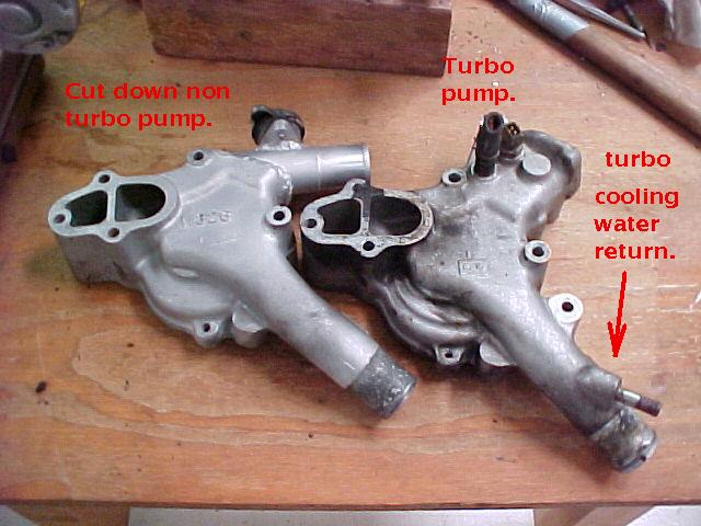
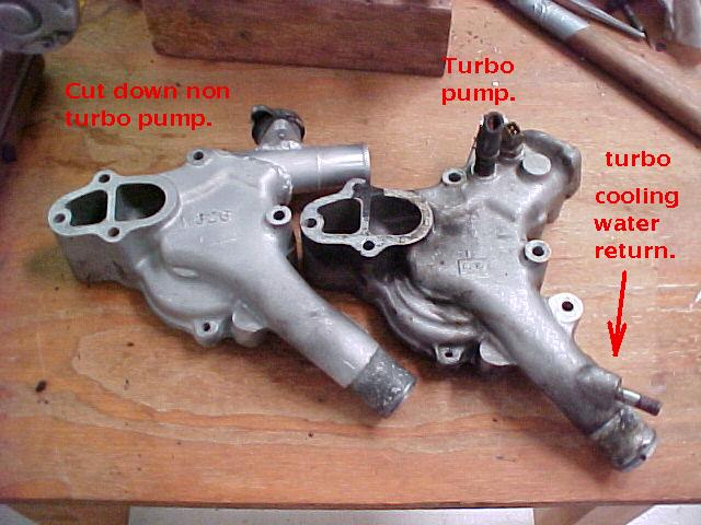
Well yes and no.
This is the REAL water pump outlet.
The straight thread to AN nipple for the turbo water supply goes
where the red arrow is pointing to the REAL water pump outlet.
The REAL outlet is drilled and taped for the nipple.
Paul Lamar
Paul,
You mean like this? I tapped the WP outlet (engine inlet) for the
oil/water exchanger I was using at the time (since been removed). The
oil/water exchanger return was connected to the WP OUT (radiator Inlet).
Sorry, I never measured the actual flow.
Mark
Thanks for the picture Mark. That is a big tap. The turbo water tap
pipe is only 1/2 inch. If your 3 rotor still cooled with that size tap I am
relieved as I was worrying a little bit about what affect that diverted water
flow would have on engine cooling.
Thanks for trying that and sending the picture.
Paul Lamar
The makers of the stock 1991 turbo obviously expected much higher water flow through
the turbo to cool it than provided by Mazda judging by the size of the
water inlet port. I was able to double the flow area of the intake port quite easily
by going up from what looks like 8 mm OD steel pipe to .5 inch (12.5 mm)
OD steel pipe. Additional flow was achieved by doing away with the restrictive
banjo inlet fitting and using a straight in metric adapter instead.
The water dran back was another matter. It was restricted by the closeness of
the turbo to the engine. No straight out metric adapters here. Only a banjo
fitting would fit. The banjo outlet pipe, if anything, was smaller than the
inlet pipe. Yesterday I had the bright idea of making my own higher capacity
steel banjo fitting using a .5 inch OD pipe outlet tube rather than the stock 8
mm. I was able to go up from 1.1" OD banjo to a custom 1.25 OD Banjo. I tried
tig welding the .035 wall .5" tube to the new banjo donut without success.
Burned through the pipe every time. I am just not a good enough TIG welder. I
decided to silver solder instead so I dug out my 45 year old gas welding set.
All the stock turbo plumbing is silver soldered as it is cheaper and quicker in
mass production. The gas valves on my old solid brass torch were frozen. I got
them freed up but I suspect they will leak. I also suspect the pressure
regulator diaphrams are shot so it was cheaper to get a new welding set from
Harbor Freight as they have a sale on till March 23rd. Dwg and pictures soon on
the new larger banjo.
Paul Lamar
--
The Rotary Engine NewsLetter. Powered by Linux.
ACRE NL web site.
http://www.rotaryeng.net
Youtube key word PaulLamar2
Copyright 1998-2011 All world wide rights reserved.