Doug in Japan::
Hope all is well
I notice Rotrex has a new small compressor that apparently spins our
direction up to 240Krpm. I hav'nt seen enough postings here regarding
traction drive compounding so I am not sure of some of the critical
details like the relative size of the turbo conjoined to size 'X'
Rotrex
I did some business with a local turbo rebuilder recently who talked
about left hand and right hand turbin scrolls. I hav'nt looked yet; my
guess is, there will likely be something that could be retrofitted to
the inlet side of a Rotrex.
I am considering modifying an Aerocharger for this purpose; if,
Aerocharger does not make a right hand turbin scroll setup.
Ed Carver
There is a bunch of stuff
at
http://www.rotaryeng.net/turbo-compound.html
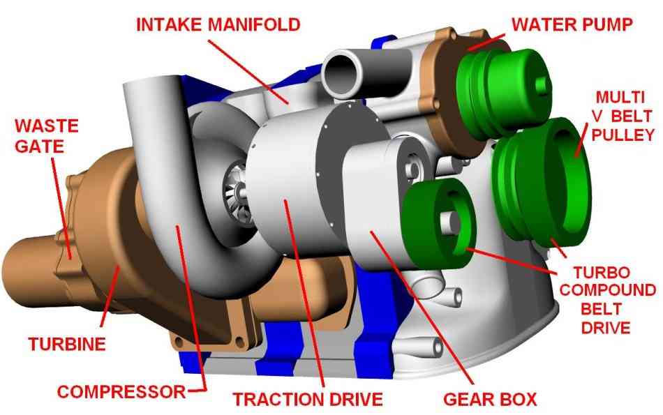
Also here are some pictures of the rotrex.
Paul Lamar
Ed,
The designer of the Rotrex traction drive told me it would work in
either direction, however the oil pump ports, the drive shaft
thread, and drive plate thread need to be reverse to turn CCW. I
haven't played with the little one you mentioned but I think it is
for motorcycles. The 13:1 ratio 30's series can handle up to about
30 hps. The 7:1 ratio 35's series up to 70hp. Turbo compound
devices increases the torque to the shaft and the final drive
pulley can get large or the traction drive outlet very small.
Matching a turbine to the traction drive is no easy trick. The
best way may be to have an axial turbine constructed by some of the
small jet engine hobbyists. Jet Beetle comes to mind.
Concept viability can be tested using a radial turbine however.
Doug in Japan
Reversing the rotation means both sides get reversed. If that is true,
then we must use a right hand scroll turbine because our engines spin to
the right, the rotrex drive to the right, and the rotrex compressor to
the right (veiwed from their respective ends. So even the small one will
not solve our problem if using a left hand turbine.
The only belt drive I know of that will reverse the rotrex pulley,
thereby facilitating our right hand drive engine and a right hand drive
turbine, is a timing belt with cogs on both sides and an idler pully
placed furthest from the crank used as the tensioner.
I believe you are suggesting that if we use a max turbine speed of
80krpm, then the compressor side of the rotrex should also be turning
the same speed at our desired engine speed. This means that both the
turbine and the rotrex outlet shaft should each have an equivalent
linear rotation speed up to our desired redline.
I suppose before the engine comes up to power, the turbine is being
driven by the rotrex until at some point the exhaust begins pushing the
turbine and power recovery begins.
I think it is time to look hard for a suitable right hand turbine with a
sweet spot on the turbine map at around 80krpm. I guess that is where
you left us before Doug. Just making sure I'm part of the way caught
with ya.
Ed Carver
This device works with most turbo's. You don't need reverse
rotation.
Paul Lamar
A lot of the reason I commented on using the rotrex, is it's simplicity
if joined to a standard turbine. What am I missing in understanding the
traction drive/gearbox setup? Is it that without a traction drive the
turbine doesn't spool properly, then you end up losing some energy?
I picked up a used aerocharger with a slightly damaged compressor wheel.
Easy fix, just had to disassemble to fix. Also wanted to know the shaft
size and design to see how worthy it might be for turbo compounding use.
Perhaps Doug can fill us in on the diameter of the two larger rotrex
output drive shafts. I don't know what 70hp means when talking about
shaft capacity. I guess it is mostly a torsional load.
Here's some picks of the aerocharger components.
The 300 thousandths shaft is also what the ceramic bearings directly
ride on. The outer bearing races are merely held in place by some shims
next to the compressor wheel, while on the inlet end, a coil spring
keeps tension against the outer race. Surprisingly simple. No oil feed,
no water feed. Just two oil wicks feed the bearings. There is a cogged
sleeve which is press fit on the shaft and keeps the compressor wheel
from spinning on the shaft and holds it in position against it's land.
Not a single nut on the whole assembly.
Are ceramic bearings magnetically attracted? These turbos are supposed
have ceramic bearings.
Ed Carver
Ed,
Direction of turbine rotation, support of side loads on the e-shaft,
orientation of the exhaust turbine, and where you want to add the power back in
(either the front or the back of the engine), exhaust manifold issues including,
structural support, thermal expansion movement, and by-pass valve, dictate the
set-up of the turbocompound experiment. I say experiment because that is what
it is at this point. To date, even though some candidate parts have been
purchased the experiment is still in the realm of a thought process.
To answer your question about traction drive units you are correct, we would
see the power passing through them backwards. To prevent confusion lets call the
drive shafts inner shaft and the outer shafts. The outer shaft contains a
pulley. In the Rotrex 30 series it is about 15mm in diameter. I'm guessing
because the unit is not on my desk now. The inner shaft is about 6mm. The outer
shaft passes high torque and low rpm.(8000-9000rpm). Say about 30hp. The
inner shaft looks wimpy but remember its' role is to pass a few pounds of torque
but power at 110,000 rpms. Losses through the unit at those power ratings would
be about 0.5 hp.
Which side the power is inputed doesn't matter; it works both ways. BUT there
is a design bias in the direction the unit was created. Looking at the pulley
side the designer wanted to match common engine rotational direction. From the
accessory side of your engine, you can agree the rotational direction is clock
wise or CW. The threads on the both shafts will tighten if the unit is run in
this CW direction. The miniature interior vane oil pump will also deliver oil
to the traction rollers when used 'as is.' Choosing to reverse the direction
the unit is turned, as I mention before, can be done, but certain components
have to modified first.
Another point to consider. the compressor wheel and inner shaft are very
light weight, the traction roller are quite heavy. Max speed is limited by
those traction rollers. The engineer who designed the unit warned me about
exceeding the rpm limits. Something about a hand grenade. He still had both
hands but can imagine their test unit had scatter shields around it. The
tolerances in this device are so severe that my unit will not turn in cold
weather. Oil temps must be maintained within 15 to 85 Degrees C. That means
proper warm-up is necessary for long life. The 35 series which are capable of
transmitting more power at reduced output ratios are larger all the way around.
The above criteria assumes a dedicated exhaust turbine connected to the
traction drive. Trying to make a turbocharger turbine drive a compressor as
well as turbo-compound unit would further complicate an already complicated
experiment.
To date I've played with many designs (on paper only) of putting the power back
into either end of the engine. Both approaches have their merits and demerits.
Remember the nature of a traction drive is to reverse rotational direction of
any power put through it. It's the nature of the beast and has to do with
limiting traction roller speeds.
For using parts pretty much 'as is' we would have to buy a Rotrex supercharger
and remove the compressor. This would be coupled to a Mitsubishi or other ??
CCW turning turbocharger with it's compressor section removed. Power would be
brought into the accessory side of the engine.
I would vote for a thermal separation between the units. The coupling between
the two would have to have a similar mass of the turbocharger compressor wheel
and be mass balanced. The design might be aluminum threaded plugs bonded to a
feather light high temperature epoxy shaft between the two units.
Power going into the accessory side would necessitate the addition of another
external bearing and support bracket there. This is something a good bell
housing design would already have. The rotary accessory side wasn't designed for
side loads required for a supercharger or turbo-compound device. The 12A or
early 13B front case is perfect for bolting something like this to. The biggest
bugaboo off course is the turbine. To optimize the system the turbine should be
designed and custom made however there are to many unknowns at the moment. One
unknown is, how much gas flow is required to boost the engine up through its
planned operational altitude? What is the turbines' TIT. rpms, MAP etc.
Knowing this would help determine how much gas flow remains for turbocompounding.
In other words at 18,000 feet is the waste gate of Dave's 13B turbocharger
all the way closed? If so what is the power setting? For instance if the
engine is at 6,000 rpm and the waste gate is closed that means the turbo-charger
is using ALL of the exhaust gas just to normalize the power at that altitude.
Said another way, there is no energy left over to run another turbine, much less
the losses through a traction drive and belt.
That would be the reason for going with a supercharger for handling the boost
end of the challenge. Yes a SC steals power from the engine, but a well
designed blow down turbine would recover that plus more.
If the answer to our question to Dave is yes I've still got exhaust gas, then
perhaps a two turbine approach is feasible. Dave forgive me if you did this
test already. Perhaps I was in Nepal and didn't get the data.
For a rough TC test, the CCW Mitsubishi twin scroll would be the least painful.
The biggest Turbocharger unit, so far as I can tell, only has an A/R of around
.76. That implies it's sweet spot would be quite a lot higher than 80,000 rpms.
The turbine wheel is tiny so it can tolerate higher rpms. That changes the
choices of the traction drive. Using this turbine as an exhaust turbine would
mean we would want to use the 30 series Rotrex traction drive. That is the one I
purchased and has a 13:1 step-down ratio. 110,000 rpm / 13 puts the output at
8461 rpm. Easily within multi-rib pulley range to match engine speed at
whatever speed is producing that gas flow. The turbine probably can't swallow
all of the exhaust flow of a 13 B, and certainly not a 20B.
Doug in Japan
You need to work on your 3D drawing skills Doug. Your ideas would come across
much much clearer with some nice 3D's. You lost me along the way :)
Side loads on the rotary accessory side from a belt drive can be
canceled to a large extent by mounting the alternator and water pump
on the other side of the e-shaft. We are only talking about 50 HP here.
In fact you don't even need to change the position of the water pump.
Just place an idler pulley between the pump and e-shaft pulley.
The water pump is taking 3 HP alone and the alternator is
is about 1.5 HP. The side load is worse with a power steering
pump and AC compressor. In any event no big deal adding
an over hang bearing or a no power balancing idler. You don't need
to feed the TC power in at the flywheel end. You do need to
isolate the turbine from the combustion torque pulses and
the V belt drive does that well.
Lets assume the engine with out TC is putting out 200 HP and has a BSFC of .47.
Fuel burn would be 94 pounds per hour or 15 gallons an an hour.
With TC and 250 HP the BSFC would drop to .376 which is down
in the diesel engine range and well below any aircraft engine on the
market. Fuel burn would be the same but it is now generating
250 HP for the same fuel.
Here is a NASA sponsored study on turbo compound rotary for
the new guys.
http://www.rotaryeng.net/NASA-Paper-turbo-compound-rotary.pdf
Go to page 156 and read Appendix C
80 HP was obtained in theory from a Mazda type rotary.
Paul Lamar
--
The Rotary Engine NewsLetter. Powered by Linux.
ACRE NL web site.
http://www.rotaryeng.net
Youtube key word PaulLamar2
Copyright 1998-2011 All world wide rights reserved.