Good morning Paul
I am sending you the propeller shaft design and i would like to know if
Jeff can machine this shaft and how much.
I specified sae 4130 but you can recommend a better choice for shafting
and treatment.
I modified my housing design for a larger surface bearing at prop side
and also a better ring gear attachment with back plate and rivets plus
bolts.
The ring gear back plate is already machined .
With Alibre i can not convert for Rhino files but dwg can be open with
Solid Works eDrawing
Jean Prudhomme
Looks good Jean. Is it an exact copy of a Lycoming or Continental
shaft?
If so that is good. Do you mean planet carrier back plate? If you
want a 2.85:1 gear box you will need to drive the planet carrier
and hold the ring gear stationary.
You will have to contact Jeff directly and see if he will do it.
If you are only making one or two you don't need an NC lathe.
jeff doddridge <
4starr@cox.net <
mailto:4starr@cox.net
<
mailto:4starr@cox.net <
mailto:4starr@cox.net
Paul Lamar
Yes Paul this is the exact Lycoming 10-540 big journal from the seal to
the flange included, i did turn around 180 degree the planet outer ring
and machined the back plate and fix with rivets a larger plate in
dia so
i can bolt it to the housing and the fact the planet stay forward i
will need a thin oil impregnated flat washer between the outer ring and
the back plate and panet housing.
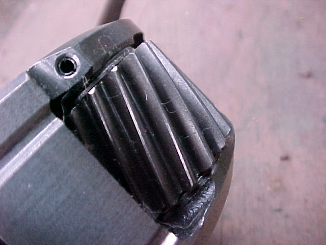
I did drive out the small gears shaft from the planet and i will make 6
longer shaft for the small gears to been driven by the propshaft and
the planet embossed reset shaft will be press fit into the
propeller shaft.
I intend to built one unit for testing and built a second one may be
more.
I will request also a quote from a drive shaft manufacturer if they
have
the material available
Jean Prudhomme
Jean,IMHO the rear flange that the planetary attaches to needs a
large radius fillet where it meets the shaft OD for the same reasons as
the flange on the other end. Also the internal bulkhead might be easier
to fabricate if the center had a conical 120 degree depression the same
shape as the largest drill bit you will use before changing to the
boring bar A boring bar small enough to machine the center flat would
be seriously overhung at that depth. The shallow end could be cut to
constant thickness by setting the compound to 30 degrees.You might
save on machining costs if you cut the billet down to .100 from all the
surfaces and have the fine finish cuts done by someone like Jeff. The
bearing journals will likely be done by a crankshaft repair shop who
could chrome the journals as well.
george grimes
Good points George. The aft steel bulkhead could be replaced by an
aluminum
plug pressed in. That would make it much cheaper to build as a
large drill can
do most of the work. See the attached jpg.
Paul Lamar
Paul, As I understand it Jean has a support bearing for the input shaft
located at the planetary end of the prop shaft and that is the reason the
rear bulkhead is not flush. Also the whole purpose of this PSRU is to
have a hydraulically controlled constant speed prop.
I am a little leary about a pressed in welch plug holding the 120 PSI
prop oil pressure.If I had to change the bulkhead I would bore it
with a step as shown in your JPEG above and fit a disk with an "O" ring
in the rim and retain that with a snap ring. The bulkhead as designed is
light and leak proof, just ugly to fabricate.
george grimes
The alloy plug would be ideal for that. The alloy plug could be two
inches
long. Hardly a welch plug. You could also add a set screw or two. I would
still press it in as the alloy expands faster than the steel. A couple
of tons will do the press job.
The only think that holds the prop on in Tracy's box is a pressed
on steel collar.
A small hole drilled in the bulkhead could feed it with oil. Since
the sun gear
rotates in the same direction as the output shaft the speed
difference would
only be about 5K RPM.
Making it easier to fab would also lower the cost.
Paul Lamar
Hi George
When you talking on the planet rear flange and mention larger fillet are
you talking as bigger end small gears shafts (6) i did make a sketch
before to you and i see a real problem to machined the counterbore with
a end mill the fact the space between the rear flange and the reverse
trust holding flange is near by and it will be much costly to produce
but as per Paul he mention on the past those 6 small shaft gears are
strong enought to transfer load from the planet to the propshaft..
Your idea with an aluminum plug with an oring and a snap ring retainer
can be enough to hold the governor pressure???May be we need also a
reverse oil seal to hold the pressure.
All your recommendations are helpfull.
The real estate slow down now so i will put more time in the project.
Is easy to removed those little shaft from the planet just tap on it
with same size punch and hammer and the rizpin cut very easy and for
the remaining part on the planet just trace a line where the pin are
located and a small corner grinding to reach the other end of the hole
which is very near and punch it out.
I was looking to buy 2 block of 4' by 8' by 12.5" aluminum at $155.00
each and it will be more economic if i built a wood casting form and get
it done by a foundry ,if one of you now a good and cheap place to get
done let me know
Jean Prudhomme
--
The Rotary Engine NewsLetter. Powered by Linux.
ACRE NL web site.
http://www.rotaryeng.net
Youtube key word PaulLamar2
Copyright 1998-2011 All world wide rights reserved.