I finally got into the gear box today and found another issue. In
addition
to the sun gear pin failure inside the gear box, the flex plate
came apart. I found a piece of it in my cowl as a litte hint of
what I was about tofind..
Here are some pictures. The plate was pretty badly broken up and
was onlybeing held together by Tracys aluminum damper plate and
the steel bolt ring. Pin in sun gear was also broken. No
apparent serious damage, just what Iassume is cosmetic galling of
the input shaft, adapter plate, and bellhousing from the loose
pin floating around.
Thinking back, I had an early sign of it at the Reno Pylon
School. Afterone of the races I noticed that my home made cover
over the flywheel hadbeen marred by the flywheel but was not in
contact with it. I attributed itto the high air speeds (205 Kts
Indicated coming down "The Chute") somehowpushing my cover down
onto the flywheel. I put some creases into the coverto make it
stiffer which seemed to solve the problem, but perhaps the flex
plate had broken at that time. With a mis-tracking flex plate it
is easy tosee that sun gear pins would be undergoing additional
stress. So I amcalling the underlying cause of both issues the
flex plate failure.
The large washers that covers the rubber dampers between the
dampers and theflex plate have made a significant groove into
the aluminum of theattachment plate. I have never noticed that
before, possibly was a functionof the twisting flex plate.
Question is, does it need to be replaced?
My rubber dampers are noticeably worn and soft and need to be
replaced. Iam getting quite a significant amount of oil coming
past either my rear oilseal or the oil seal on the gear drive.
That oil may have done in therubber dampers, that got too sloppy
and stressed the flex plate thateventually fatigued and broke,
which further lead to the pin failure.
So I am undecided on what to do about the flex plate replacement.
I agreethat the iorn flywheel is not the answer. The machine
work would have to bequite extensive, because the aluminum plate
rides inside the ring. Afterall that machining, it would have to
be re-balanced but that would bedifficult because it has the rear
counter weight built in.
Using one of the aftermarket aluminum flywheels might work. It would
still
have to be machined to make space for the damper plate, but at
least itwould be aluminum (easy to machine) and could then be balanced
symmetrically
(perhaps even with the damper plate installed so it is all nicely
balanced.
That would not be a low cost solution, however!
Paul, if I were to get an aluminum flywheel like this one:
http://www.racingbeat.com/RX7-**1986-
1992/Flywheels/11465.html<
http://www.racingbeat.com/RX7-1986-1992/Flywheels/
11465.html
do you think that you could put it on your milling machine and
mill in theresesses for tracys damper plate? Then would you have
any suggestion onwhere I could get it balanced?
I am also wondering if I have any business trying to make that
much HP. Iwas about to install a water/methanol injection system
to be able to usemore boost at Reno. But it seems I may not be
able to safely use the HPthat I already have...
-
--
David Leonard
Turbo Rotary RV-6 N4VY
http://N4VY.RotaryRoster.net <
http://n4vy.rotaryroster.net/
http://RotaryRoster.net <
http://rotaryroster.net/
Wow Dave that is a game changer.
I have a guy up here in SZP with a really big lathe that can make
a new "flex plate" . As I recall the subject of flex plate run
out came up recently. Perhaps your plate was warped. Everybody
should check their plates for run out. Any run out puts a bending
stress on the plate due to dynamic imbalance. All parts of the
plate want to revolve in the same plane. If the plate does
not track it will introduce a bending stress in the material.
Also the alignment of the input shaft to the box must be
perfectly in line with the e-shaft axis. This is not easy to
check. Perhaps a low cost laser can be inserted into an empty
gear box starting at the prop bearing end and see where the light
spot falls on the counter weight. A holder for the laser can be
made and checked in a lathe for an aligned axis. If you UPS your empty
box,spacers and adapter plate up I'll put Jim Poole on the job.
One quick and dirty way is to assemble Tracy's damper on the
input shaft with out bolting it to the flex plate. In fact
leave the flex plate out and off for the moment. Use the engine block
as an anchor for a dial indicator and check for damper plate run out.
Then measure the distance from the block to all four quadrants
of the damper plate.
Paul Lamar
Dave if you look on the RX-8 flywheel as been redesign by Mazda
and those 4 holes 1" dia plus are located further apart as the
center of the flywheel and close to the ring gear It looks to me
Masda had similar fatigue problem with the RX-7 flywheel.The
problem we can not fit the Tracy damper plate because it does not
fit the attaching holes and are to close of the ring gear unless
someone have an other solution
Jean Prudhomme
Yes, it is becoming pretty clear that any option other than the
auto- tran flex plate is going to take considerable extra work to
get it addopted. I think the aluminum fly wheels are my first
choice of alternative at this time, but I may just put in the flex
plate and stop trying to make a lot of HP.
--
David Leonard
Turbo Rotary RV-6 N4VY
http://N4VY.RotaryRoster.net
http://RotaryRoster.net
I would not use aluminum Dave. IMHO a better way is use fatigue resistant
.065" thick 4130 sheet reinforcement tig welded in the center
diameter. I'll build you one out of a spare plate I have if you
will work on finding a replacement.
Paul Lamar
Hi Dave,
I gather from your e-mail and web that you are a Naval Aviator. This
would
tell me you are used to aerobatics, which will put assorted higher
stresses on
the airframe. I was having a morning coffee and contemplating navel
lint when
I came to the idea to check your web and construction photos. Also this
came
to the forefront after the pylon school with high stresses.
Your PSRU mount on the plate has a fairly small diameter ring of bolts.
During
aerobatic manoeuvres, there will be a large torque on the prop that
will be
transmitted through the PSRU to the mount plate. I believe the flex
should be
determined and dealt with.
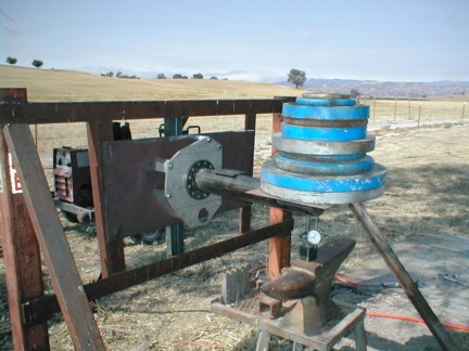
So, how to measure and calculate the flex force. A hydraulic cylinder
like
used with a pump for body work can be modified to have a pressure gauge
and
the cylinder diameter is easy to find. This will tell the pounds
force. If
this cylinder is extended a bit (1/2 stroke) and a bottle jack is
used under it to apply force, then a dial indicator will show the
amount of flex. Put the hydraulic jacks under the front of the PSRU
just behind the spinner. A piece of angle or channel iron bolted on
the top of the engine (the lift bracket bolt hole) will provide a
mount for a dial indicator, to read movement on the top of the front
of the PSRU. Paul should be able to do a quick calculation of the
force applied through the prop during turns.
You may need to install braces from the front of the PSRU back to the
engine
bellhousing bolts to stiffen it up. A small amount of flex is like a
misalignment and under load it will not take long to break the flex
plate.
Brace to the sides as well.
Dale Davies
David I sent an idea of using the RX_8 flywheel with an additional
aluminum
plate,the RX-8 look a stiffer design
Jean Prudhomme
Yes it does look stiffer Jean but it would require a new Tracy
style damper plate because I suspect it is larger in diameter.
I think the cracks started in these holes.
The 13B plate is only 1.5 mm thick or about .059".
I think the holes could be filled in with .065" thick 4130
and it would be much stronger. Also a 4130 doubler plate
could be added to the center. This is all low cost.
Aluminum is not a good material for this use.
Paul Lamar
--Hi, a flex plate will flex. Our experiance with an odd fire
Chevy V-6 on a dyno showed more than 1/2" deflection at the ring
gear on a heavy duty racing flex plate judging by the notches cut
into the ribs at the back of an expensive aluminum block. The ring
gear is effectively the rim of a gyroscope. The unbalance of the V-
6 excited it. With the better balance of the Wankel that would not
be a problem but maneuvering in the aircraft would be. It needs to
be stiffer to minimize deflection and fatigue. Look forward to
seeing you all on Saturday. Free lunch after meeting.
Murry Rozansky
Like some fast 2 G laps at Reno? :)
A one radian per second spin will bend a Lycoming crank shaft flange.
Good call Murry. Aluminum is not what you want when continuous
bending is present.
---------------------------------------------------------
Here is what the Skyranch Engineering Manual has to say about it.
It is obvious from this point of view Tracy's large nuts and bolts
out near the rim add to the moment of inertia. Helicopters deal with
this by putting hinges in the blades near the hub. Obviously it is
not a good idea to use a solid and stiff disk such as an aluminum or
steel flywheel as that adds a lot of weight. Stresses in the solid
hub go up to high levels. It is better for the rim of the flex plate
and ring gear to find its own plane of rotation and allow the plate
to flex. If it is laminated from two or more thin spring steelplates
the cyclical bending stress on any one plate will be lower.
Does anybody wish to comment on this analysis or scenario?
* Sky Ranch Engineering Manual. This book presents an excellent
overview of the problems of aircraft engines. It is 500 pages and a
bargain at only $23. There are many details on the materials and
processes used to build a successful aircraft engine. There is a
very good and exhaustive discussion of destructive torsional
vibrations and fatigue. The telephone number to buy this book is
(916) 421 7672. The author is John Schwaner. John is highly thought
of in the experimental aircraft community.
Paul Lamar
I would caution against re-inventing the wheel. I think the flex of the plate
between the PSRU and the rear iron/bell housing bolts needs to be checked. The
flex plates between a 600HP diesel and a generator are four thin discs about
0.020" thick. That boils down to about 1750 lb-ft at 1800RPM. The alignment
MUST be checked or the plates will buckle under load.
If 600 to 700 pounds does not flex the aluminum plate much, then OK. The
pounds is from the gyro force calculation and is pounds force not PSI. Use the
method I described in my previous post to measure the flex. If the initial
alignment with the bolt-up to the flex plate is good as per OEM standards,
then the flex plate should not break! I believe it is the PSRU mount flexing
because the gyro forces go through it and are counteracted by the engine
mount. When the PSRU plate flexes, the force is transfered to the flex plate
which eventually fails. Planes that are not flown as aggressively likely will
not have a problem with this. Putting a doubler in will not hurt, but the
welding could be a concern. If it could be put in as a sandwich between the
existing bolts would work well.
Again, I suggest measuring the PSRU mount plate flex.
Dale Davies
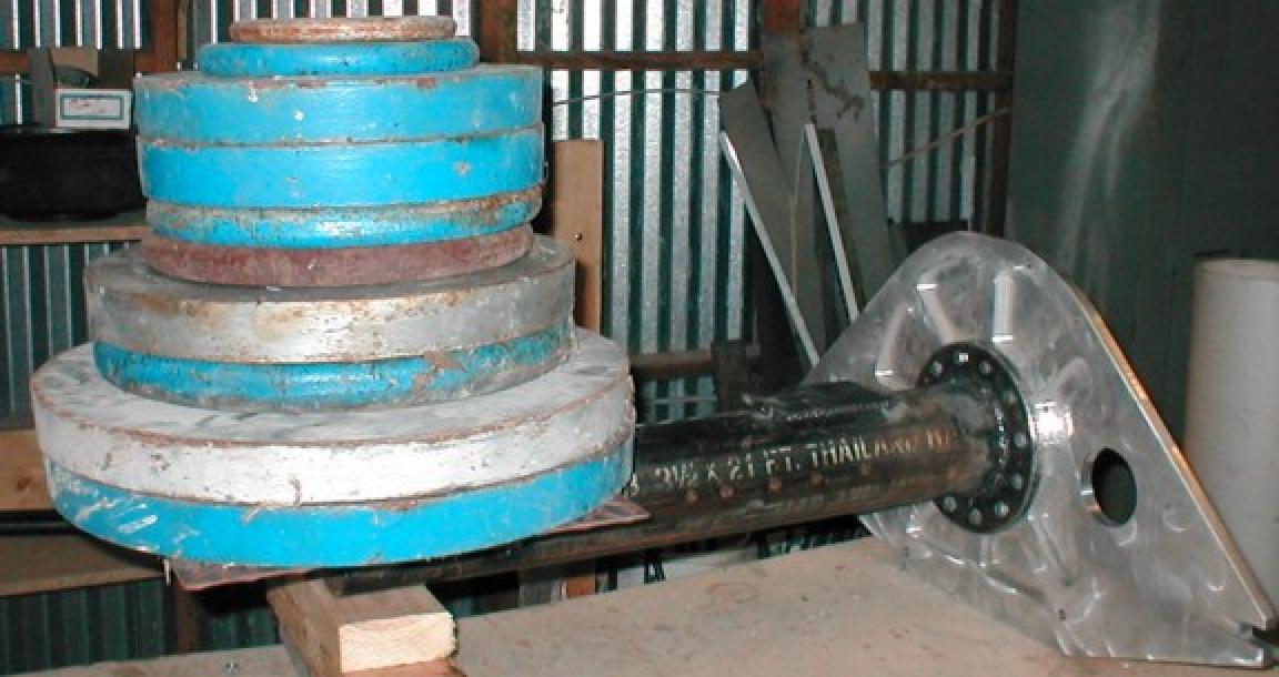
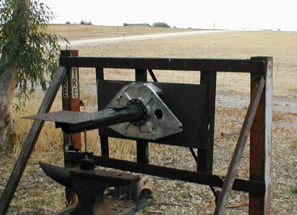
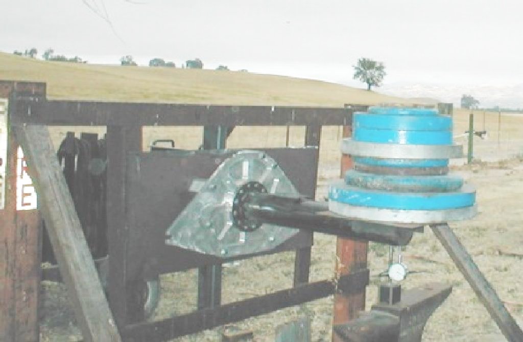
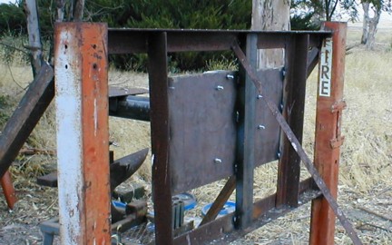
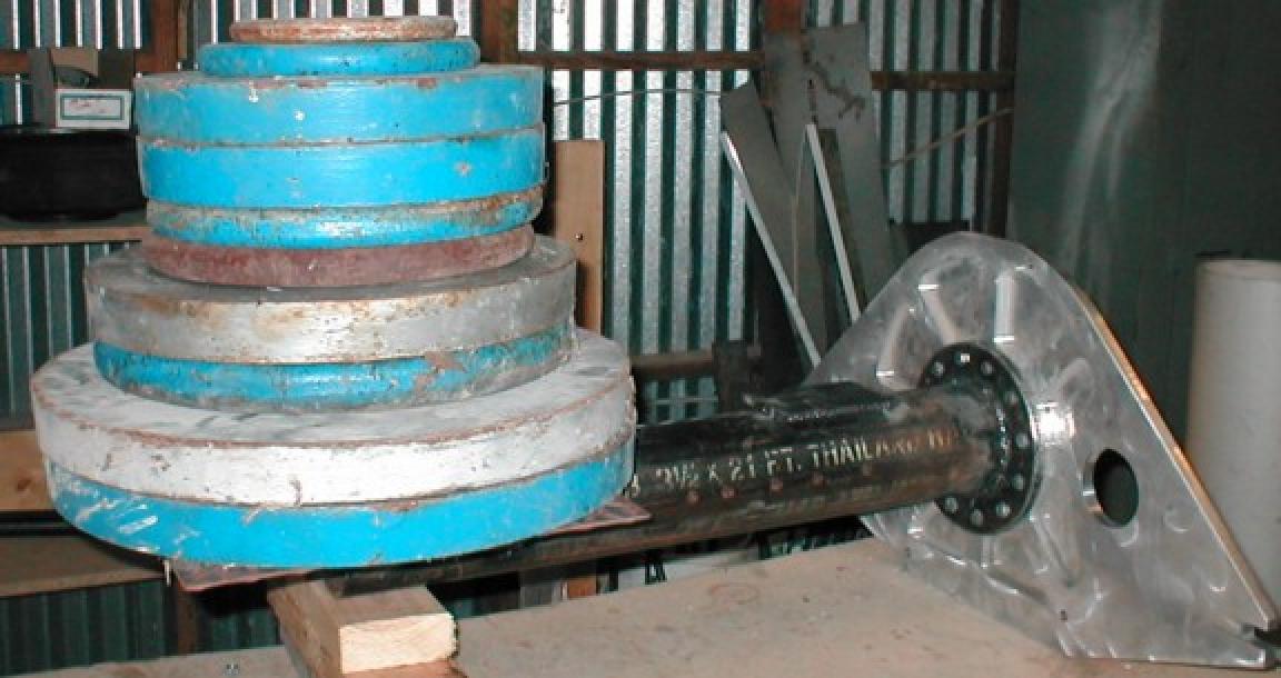
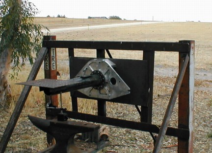
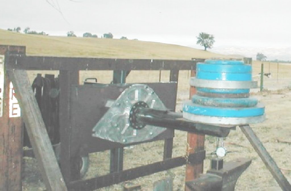
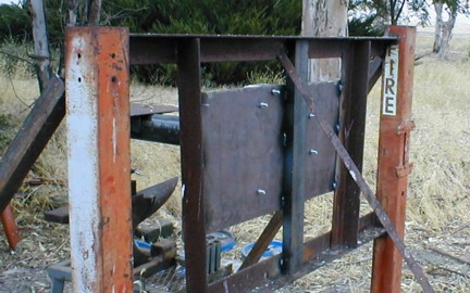
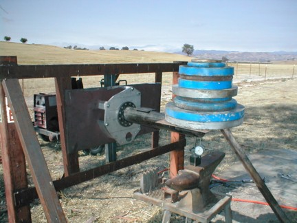
We did that Dale and the half inch 6061 plate was amazingly stiff.
Tracy's spacers between block and plate could be better.
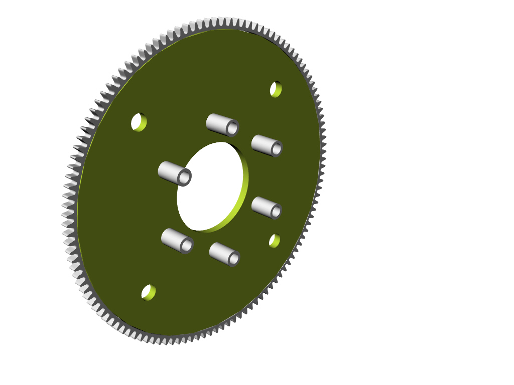
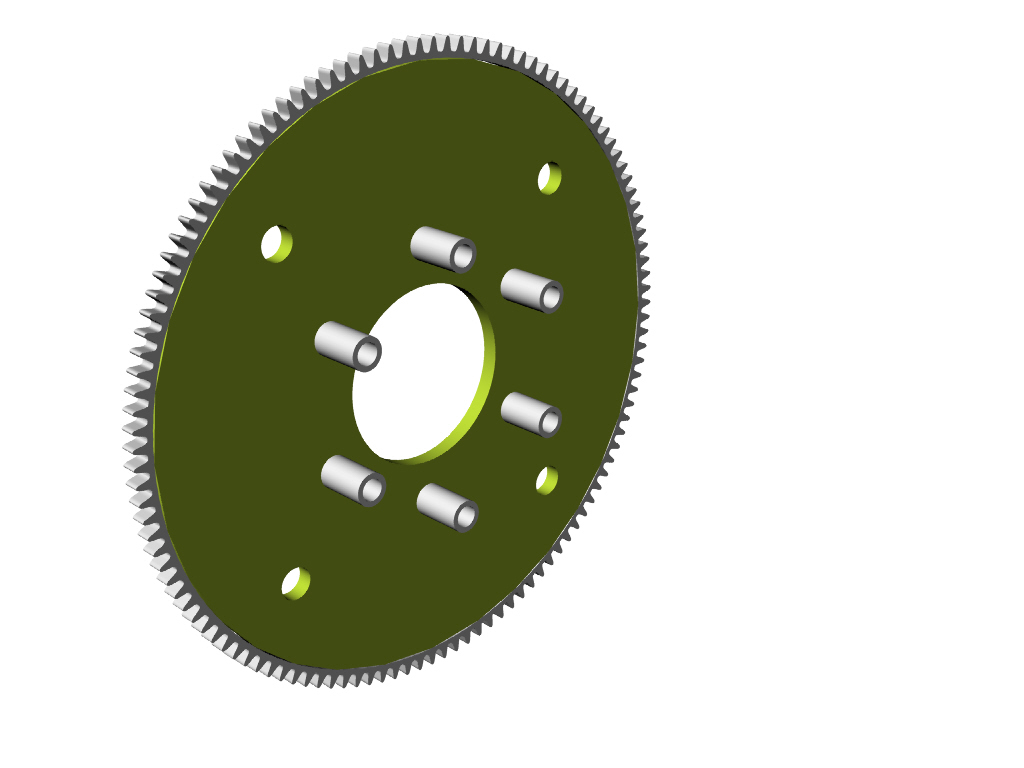
One could also make a simple flat 4130 flex plate and space it out
out from the counter weight to get the ring gear in the right location.
Here is a 3D.
Paul Lamar
--
The Rotary Engine NewsLetter. Powered by Linux.
ACRE NL web site.
http://www.rotaryeng.net
Youtube key word PaulLamar2
Copyright 1998-2011 All world wide rights reserved.