Why is it important when dealing with flex plates?
http://en.wikipedia.org/wiki/Moment_of_inertia
"In classical mechanics, moment of inertia, also called mass
moment of inertia, rotational inertia, polar moment of inertia of
mass, or the angular mass, (SI units kg·m²) is a measure of an object's
resistance to changes to its rotation. It is the inertia of a
rotating body with respect to its rotation."
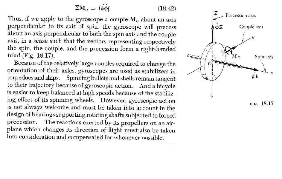
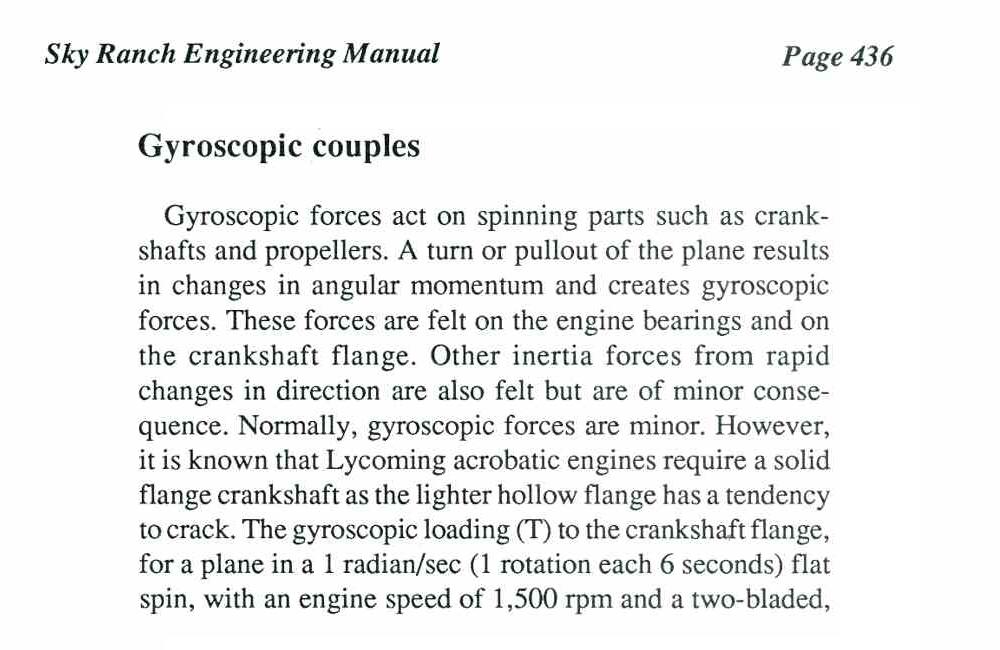
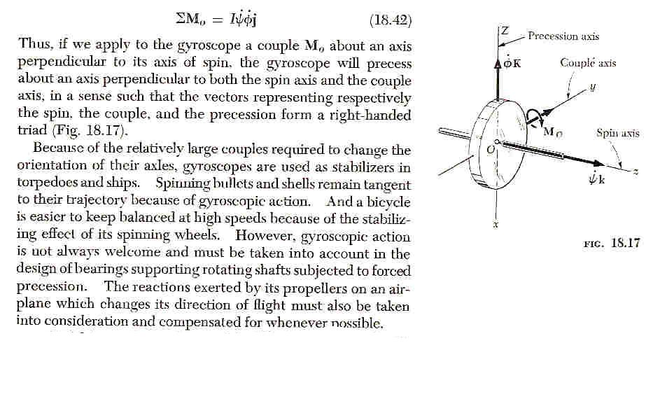
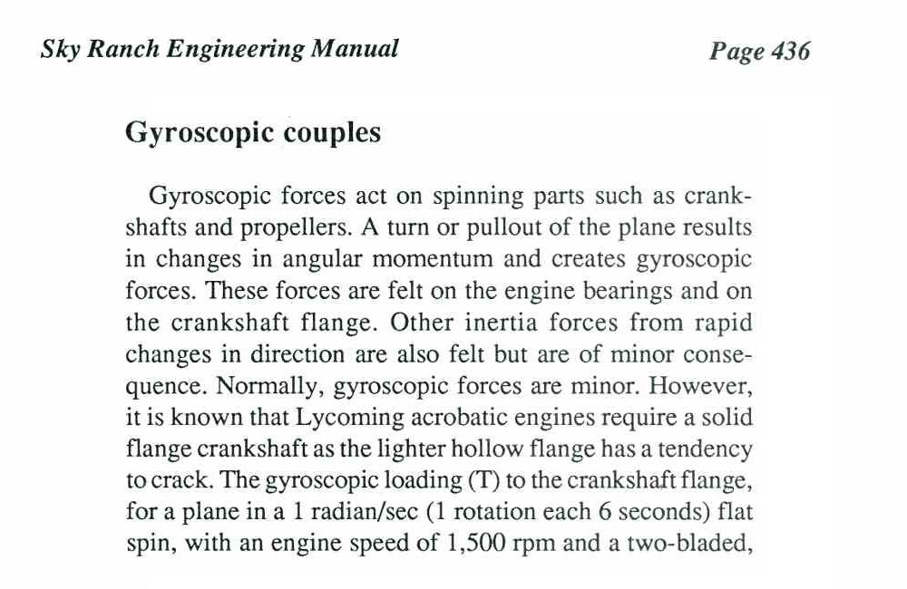
Also read gyroscopic forces.
http://www.gyroscopes.org/behaviour.asp
"When the gyroscope is spinning it can contain large amounts of
stored energy. Newton's first law of motion states that any body
will continue in its state of motion (still or traveling) until
outside forces change it. Because of the forces when the gyroscope
is spinning, if it is moved the gyroscope will try to 'compensate'
for this movement. If we take the example of a gyroscope's axle
being clamped to the structure of the car (often the cars engine
behaves as a gyroscope because of its shape, mass and rotations)."
"If the gyroscope/engine is spinning at a fairly high speed in a clockwise
direction, as seen from the back of the car and as shown in the diagram
above. When the car is turned to the right (clockwise from above)
forces A and B are applied to the structure of the car forcing the
front end of the car down and the back end up. If the car is
turned to the left then the front end of the car is forced up and
the back end forced down. If the gyroscope is spinning in the opposite
direction then the reverse will happen."
"However if the car was moved directly upwards, downwards,
forwards, back-wards or side-to-side the gyroscope would not
apply any extra forces. The gyroscope only applies extra forces
when the car is moved at an angle
(turning left/right or when the front/back of the car is moved
up/down). This effect is known as gyroscopic precession."
These forces go through the flex plate out to the ring gear
stressing the flex plate back and fourth near it's hub thousands
of times per minute. In other words the ring gear attempts to continue
to rotate in it's original plain while the hub is being forced to
change direction.
Paul Lamar
I agree that there is gyroscopic forces that affect the rotation
of the flex plate. Also included with that is the toque converter which
has a much greater mass. Any movement that would take place is held
in check by the index hub on the converter that goes into the back
of the e-shaft or crankshaft and the bearing in the transmission
pump. I am not sure the clearance of the bearing, but 0.002" seems
reasonable. That would imply 0.001 movement which would be minimal
flex in the flex plate. I am inclined to think the failures are due
to the torque pulses applied to the flex plate under high
continuous power loading. I believe you are right with the idea to
make a flat disc of water jet cut stainless and tack weld the ring
gear on. Lightening holes around the outer diameter will not fail
in my opinion. But then what do I know as a burnt out mechanic :-))).
Dale Davies
-
Dale,
I am lost with what you are trying to imply with the clearances.
But my conclusion on the RD-!B failure comes from this lecture on line.
As it is stated there, it is "VERY NOT-INTUITIVE". The part about
gyroscopic forces starts about 14:20 into the video.
http://www.youtube.com/watch?v=zLy0IQT8ssk
I must say I tend to agree with Paul that Torsional Vibration is
not the problem here, and Mazda Rotary does not seem to have a Torsional
Vibration Problem as is typical in piston based engine. So the RD-
1B failure should be mainly due to metal fatigue of the flex plate.
One solution is to use a very stiff flywheel from a manual
transmission instead of a flex plate/ring gear combination. If the
flex plate is eliminated, the precession force is transferred to
the shaft, onto the bearings, and eventually to the aircraft
through the engine mount, but the solution is heavier than a flex
plate/ring gear combination.
I think that for normal flying, a flex plate/ring gear combination
is sufficient. But for people with acrobatic in mind, a flywheel is
a better choice.
Henry Nee
My point is that the flex plate by itself without being coupled to
the transmission could flex from the gyroscopic forces. The torque
converter and the bearing in the transmission prevent any movement
from taking place. Without movement, there will be no fatigue from
the gyroscopic forces. I was asking about this earlier and Paul
educated me that gyroscopic forces at Reno will be minimal.
Aerobatic will impart more, but that is controlled and dissipated
out through the bearing in the PSRU, mount and to the airframe.
I now believe the fatigue is starting from the twice per rev
loading and unloading with regard to the compression and subsequent
combustion. This is applied at the center of the flex plate and
resisted close to the outside diameter. The drive plate with
isolator rubbers are bolted closer to the OD, where the resistance
to the rotation is applied. The holes near the e-shaft mount bolts
are a weak link due to the reduced amount of metal to transmit the
power pulses through. You do not need movement and flexing to
generate fatigue in metal. Look at conn rods that break. If they
have not been subjected to stress from over revving the engine, the
break started from a surface imperfection that allowed loading and
unloading of the rod to crack from fatigue. When you look at a part
that has been fatigued, the break looks like it crystallized. When a
part is torn apart from some other failure such as over rev, the
separation point looks different.
Mark S has experienced a failed flex plate without the aerobatics,
so that bit showed me it is not a direct cause of the manner the
plane is flown. It must be a factor of design and the limits it was
designed for. The factory designs the flex plate with a low duty
cycle in mind. 30Hp out of say 210Hp available is light load. In a
flying plane the engine is working at max power for 5 to 10 minutes
and the cruise at 60 to 75% possibly for hours. The flex plate was
not designed for this.
With this in mind, I think Paul's re engineering with a flat SS
plate of
0.090 to 0.125 thickness will cure the problems. It does not seem
that Tracy's isolators are a source of trouble, but a rethink on
them may also be in order as Paul is proposing.
It all comes down to weight and designing for the application.
Mazda is concerned with weight in the cars as the builders of AC
are. It is the duty cycle that Mazda did not have in mind. They did
not use these parts in the Le Mans engine.
Dale Davies
Henry,
Thank you for pointing out that physics video. I found it quite informative. I
still think the flat plate drive is the answer. A series of lightening holes
close to the outside will reduce the mass and thus the gyroscopic precession.
With the index in the e-shaft and the bearing in the re-drive there can not be
much flex. Possibly with the stock flex plate having the holes close to the
center and the mass farther out it can flex slightly on the rubber isolator
bushings. If the holes are moved farther out and the center is solid the plate
will stand up better.
Dale Davies
Dale,
Glad you like the video. It reminds of of the good old times in
school. Anyway, I agree that a flat plate is better than the flex
plate, and I think David Leonard is lfying with an actual rigid
flywheel now.
I was hoping to be clear that the flex plate, at the connection point
to the e-shaft, is rotating at the original plane during a turn, but
the ring gear, due to precession, is rotating at a different plane.
And the flex plate flexes back and forth as it rotates to accomodate
that.
If we are using a rigid flywheel, the precession force generated
during a turn would be off loaded to the bearings, etc. as you pointed
out.
As Paul also said, the flex caused the flex plate to bend, back and
forth once every evolution, and that is about 7,000 time a minute. The
bending happens at the weakest point in the flex plate, the metal
between the round holes, eventually metal fatigue set in, and the
plate cracked.
As for the HP doing the damage, I think it is possible, but unlikely.
A better story would be the number of flying hours Mark S. has
accumulated. As even with the smaller precession during lower G turns,
the plate still bends back and forth at 7,000 times per minute, just
not bent as far as in David's flex plate.
Henry Nee
The flex plate rim only rotates in the original plain briefly. It eventually rotates
in a the new plain unless the airplane continues to turn which happens at Reno.
One flies in circles at Reno. The forces and stresses are still there regardless
of how stiff the plate is. In fact the stress may be higher. A hinged helicopter rotor
is a good example. The hinges drastically reduces the stress on the hub as the helicopter
rolls or pitches up and down. A flexible prop blade constructed with fiber glass
or wood puts less stress on the prop shaft than aluminum or steel blades.
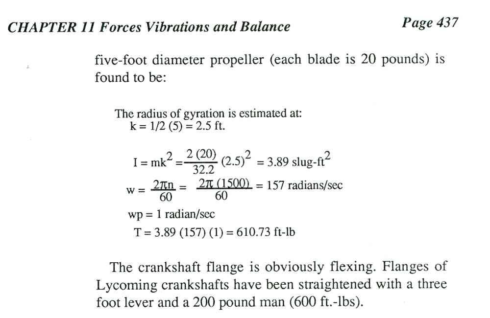
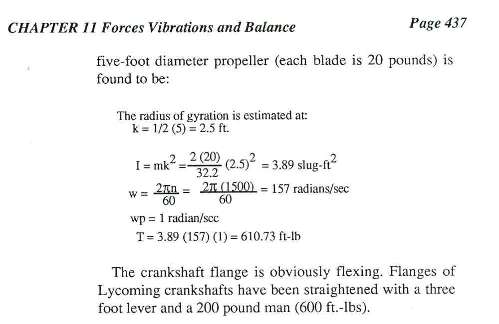
With a 50 pounds constant speed aluminum prop 600 foot pounds of bending torque
is placed on the Lycoming crank shaft at a 60 degree per second turn rate.
That is enough to bend the prop flange. Lycoming beefed up the flange for aerobatic
engines. One can instantly break a direct drive 500 ci Cadillac V8 crank shaft by jumping
over a hammock in the Everglades.
Paul Lamar
The Rotary Engine NewsLetter. Powered by Linux.
ACRE NL web site.
http://www.rotaryeng.net
Youtube key word PaulLamar2
Copyright 1998-2011 All world wide rights reserved.