With a rash of loss of power episodes, and with the lack of a definite cause, and with a common
thread being that they had a Hushpower muffler, I'm thinking of either or both of these options- rip
the guts out of my current hushpower muffler, or design and build a muffler that is the same
dimensions as the Hushpower. It needs to have a 2" inlet be about 18" long, and be no wider than 4
1/2 inches in diameter. I'm thinking of ordering or making 2) 2 inch to 4 inch transitions made
from .065 321 stainless, with a center section that is cylindrical. I want something that is not
going to have it's guts blow out and obstruct the exhaust flow and kill power. It should also
attenuate the exhaust note to some degree.
When I last checked my Hushpower, I took it off and it rattled like a baby rattle. I used a flexible
camera and both inlet and outlet cones were intact. Still, this muffler is the thing that makes me
most nervous about my installation.
Any ideas for the internal design of a muffler that is the same rough dimensions as my hushpower,
but is somewhat failure tolerant?
I have one of those cylindrical SS mufflers made in Canada, I forget the name of the manufacturer,
but it is cylindrical and about 24 inches long. It has angle pieces welded across the cylinder part
in a spiral pattern. I might just cut it and shorten it to fit.
Thanks,
Brian Trubee
Is Boeing surplus still up there? If you can get some inconel that would be a way
to go. .065" 321 SS is pretty good. I would design it in two pieces and bolt them
together with 1/4 inch SS bolts. That way you can take it apart from time to inspect it.
Paul Lamar
P,
Idea: Incorporate a turbocharger waste-gate type device...?
If the pressure inside the muffler gets abnormally high, the waste gate opens and allows
free-flow of exhaust gasses. Could be a "Y" connector before the muffler.
Jack Beale
http://www.audioholics.com/education/acoustics-principles/helmholtz-resonant-absorber/helmholtz-resonant-absorber-page-2
http://tinyurl.com/3g6eejb
For resonators designed to be used at very low frequencies a minimum diameter of 2" should be
considered - and be of sufficient side-wall thickness that it does not readily collapse. This
project uses 68mm (2.7") PVC downspout piping, which fills the criteria, and is extremely cost
effective - sufficiently so that cutting several lengths for tuning purposes adds little to the
overall project cost.
4. Measurements.
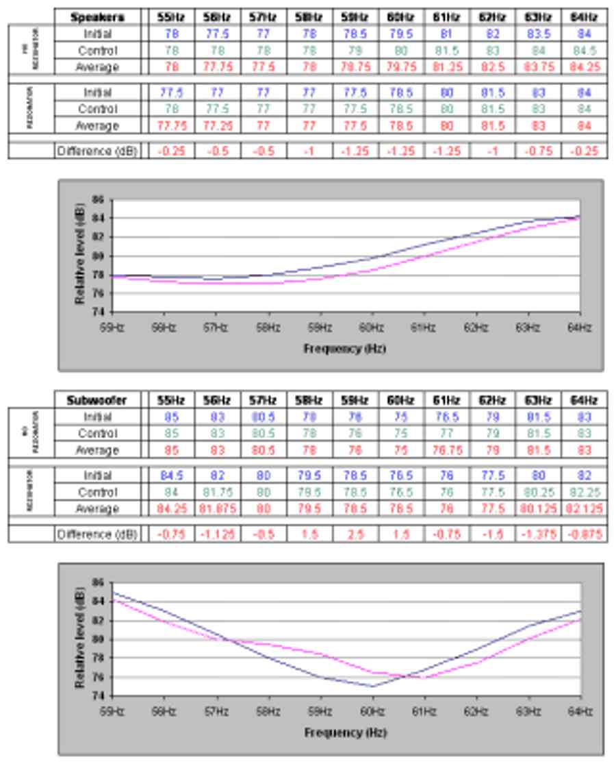
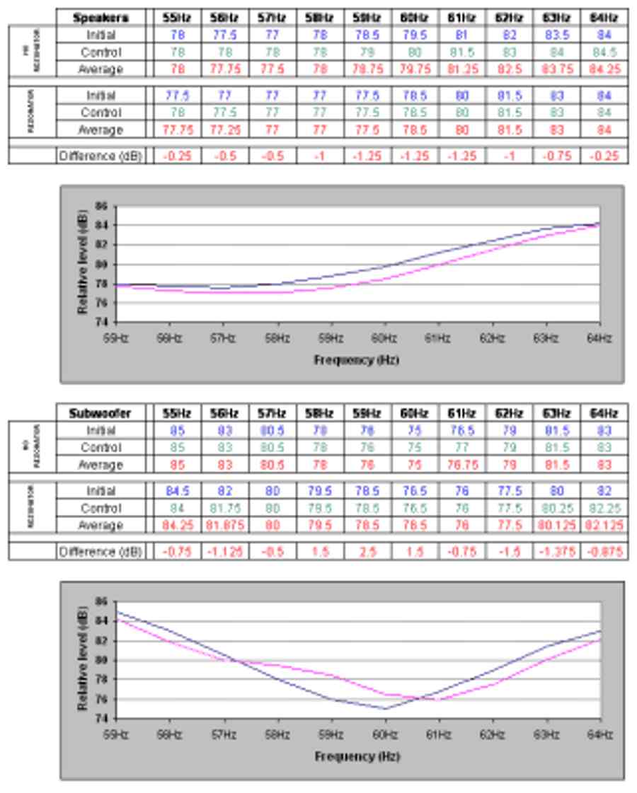
The project resulted in two identical Helmholtz resonant absorbers, now tuned (after the design
addition of acoustic wadding to increase bandwidth) to about 60Hz. The following results are the
final sets taken, and those now being used in the target listening room. The first set being those
from the primary (hifi) loudspeakers, and the second set from the home cinema subwoofer - the
differences in response are marked, and highlight the effect that frequency response and level of
low bass (particularly) have on room response.
Bear in mind that the results for the primary hifi system, the one around which this project was
based, shows smooth, but quite subtle losses - the primary benefit of decreased resonance is not
shown. As with many, if not all passive acoustic treatments, it may be necessary to use additional
units to produce the desired response.
4.1 Measurement notes.
Each run of measurements has an initial set and a control set. As the measurements were for
comparison purposes, not specific SPL levels, care was taken in the provision of a control set to
reduce spurious readings or read errors. The results were entered into an Excel spreadsheet and an
average taken between the two sets of measurements. The averaged results are those used in the
following graphs.
All measurements were taken using an analogue Radioshack SPL meter, using single frequency test tones.
http://www.audioholics.com/education/acoustics-principles/helmholtz-resonant-absorber
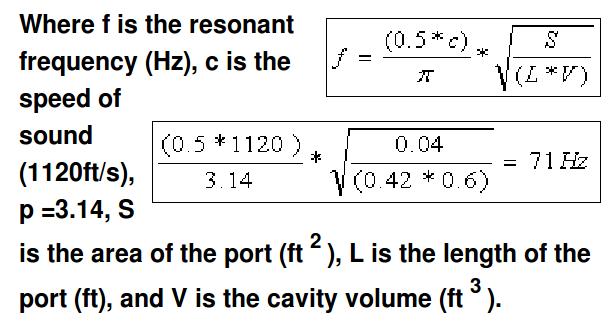
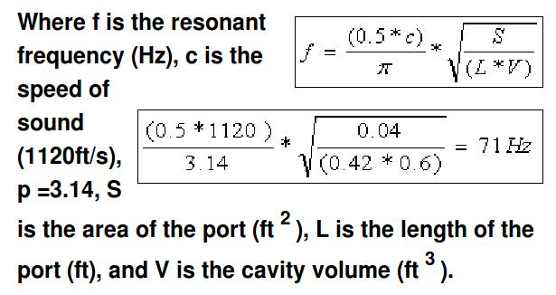
The formula for calculating the resonant frequency of a Helmholtz resonator is:
See simple-helmholtz-formula.jpg
Note the requirement that the units of measurement are constant. The example uses feet, but could be
substituted for meters. Despite the simplicity of the equation there are many measurement variations
that the designer will face. Therefore, it is highly recommended that the equation be programmed
into a spreadsheet, allowing the designer to see instantly the effect each measurement change has on
the design. The following Excel spreadsheet includes such calculations (including port
end-correction), as well as a basic axial room mode calculator, which is useful for initial room
mode mapping.
http://www.apsalisbury.dsl.pipex.com/modecalc.xls
Paul Lamar
--
The Rotary Engine NewsLetter. Powered by Linux.
ACRE NL web site.
http://www.rotaryeng.net
Youtube key word PaulLamar2
Copyright 1998-2011 All world wide rights reserved.