Let's try this link.
http://www.lexami.com/pdf%**20files/rd-1c%20manual%20and%**20photos.zip<
http://www.lexami.com/pdf%20files/rd-1c%20manual%20and%20photos.zip
William Hagood
That works, looks like the prop shaft small end actually centers in and
rides in the bronze bearing in the big end of the sun gear. The sun gear
has
one pin passing through the input shaft. What I can't see is what the back
side of the sun gear looks like inside. One of the images shows the bronze
still in place, so I guess that is what I would see.
I have all of the planet related parts. I do not know what was done to
make
the input shaft. At least two of the shafts in the trans have the correct
spline, the center shaft and another, one of the long shafts. The center
shaft inside bore is too large to be modified to fit inside the sun gear.
The other long shaft would need a sleeve to bring the OD out to the size
of
the planet ID. The photos of the input shaft do not appear to show a
sleeve.
I can't quite tell what the input shaft thrust bearings are supposed to be
thrusting against. To do the new damper, should these be riding against
the
modified drum to keep it from moving rearward?
I'll be working on getting the damper plate made, then after that is
sorted,
maybe work on building a tube shaft unit just for the sake of saving
weight
and designing it to carry its own gear lube and pump. Almost everything on
the planet end will be similar according to Pauls drawings. The tube shaft
will need to be driven by the planet in a different fashion.
Thanks again William.
Ed Carver
You may have to have the input shaft machined Ed. Some of the latter
sun gear ID's are too large for the stock parts to be easily adapted.
The thrust comes from the helical sun gear trying to unscrew itself.
The load used to go into the e-shaft needle thrust bearing in the front
of the engine. That only lasted about 500 hours at relatively low
power in those days. Ross added the thrust bearings in later boxes
but Tracy discovered that on his own.
There is a long history there.
Paul Lamar
That means we cannot push on the rubber damper assem, and need a spacer
between the plate that presently takes the thrust from the sun gear, and
the
surface of the drum to keep the damper from walking back from the flex
plate.
Well, dang, the splines might be toughest part then.
Ed Carver
I am not sure I understand what you are saying here.
Try making as sketch of what it is you are saying.
The female splined bulkhead will bottom out on the end of the splines. If
there
is some rubber expansion in the damper it will tend to reduce the force
on the helical gear thrust bearings and transfer that same force to
the e-shaft thrust bearing at the front of the engine. Currently there
is no load on the e-shaft thrust bearing.
Now it is possible to design the concave rubber blocks with enough
expansion
clearance so no axial force will be generated.
Paul Lamar
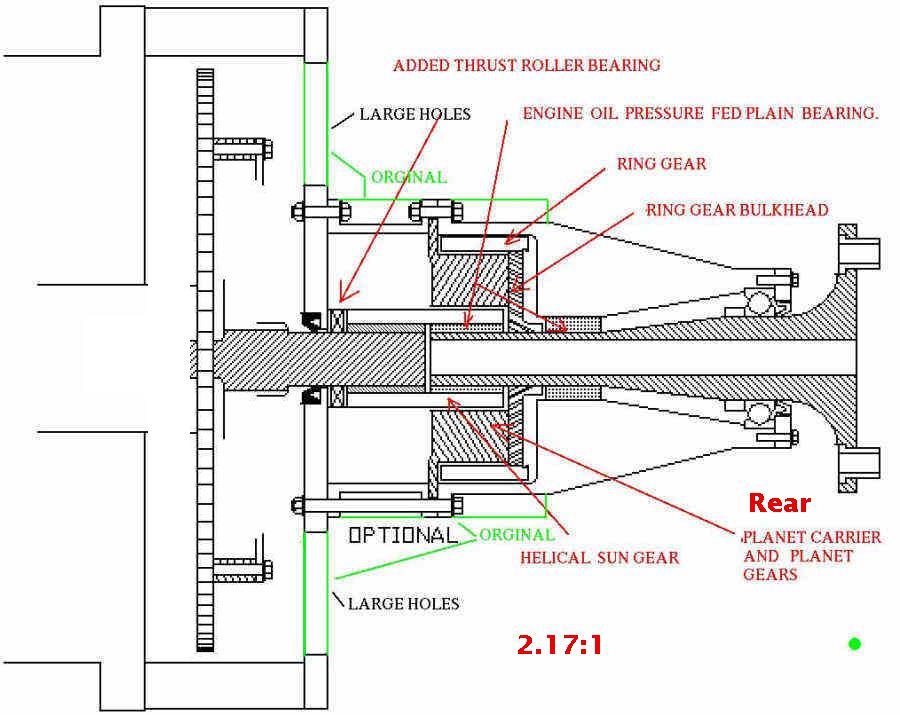
The drawing shows the sun gear thrust bearings thrusting against the "bell
housing". Not shown fully, is the female splined drum, but we know it is
there. I am assuming we want the input shaft pilot to ride in the pilot hole
of the e-shaft. The drawing seems to show the end of the shaft splines
butted up against the e-shaft.
The photo has the input shaft passing through the drum splines presumably to
rest in the pilot bearing. There is a space between the the thrust bearings
of the sun gear, and the face of the drum splines. It is this space that may
need to be filled with something. Perhaps more thrust bearings inside the
bell. I can't see what will keep the damper from moving from it's place If
we don't.
Your new damper does not appear to extend as far out from the e-shaft as
Tracys damper does. So what am I missing if anything? Are you saying that if
the damper moves out, that it will just stop against where the splines end.
The photo appears to show the shaft as just described.
Really though, I don't need to know this. I just need to build the damper
the way you want. I can sort out these spacing issues when the time comes to
create an input shaft if I want. And so long as you are fully aware of these
dimensions, there will be no problem.
Ed Carver
Dave had to shorten the female splined plate to get the flywheel in there
so you have that adjustment. The current length of the spline is more
than enough to transmit the torque.
You might want to mock it up in cheap steel.
Paul Lamar
--
The Rotary Engine NewsLetter. Powered by Linux.
ACRE NL web site.
http://www.rotaryeng.net
Youtube key word PaulLamar2
Copyright 1998-2011 All world wide rights reserved.