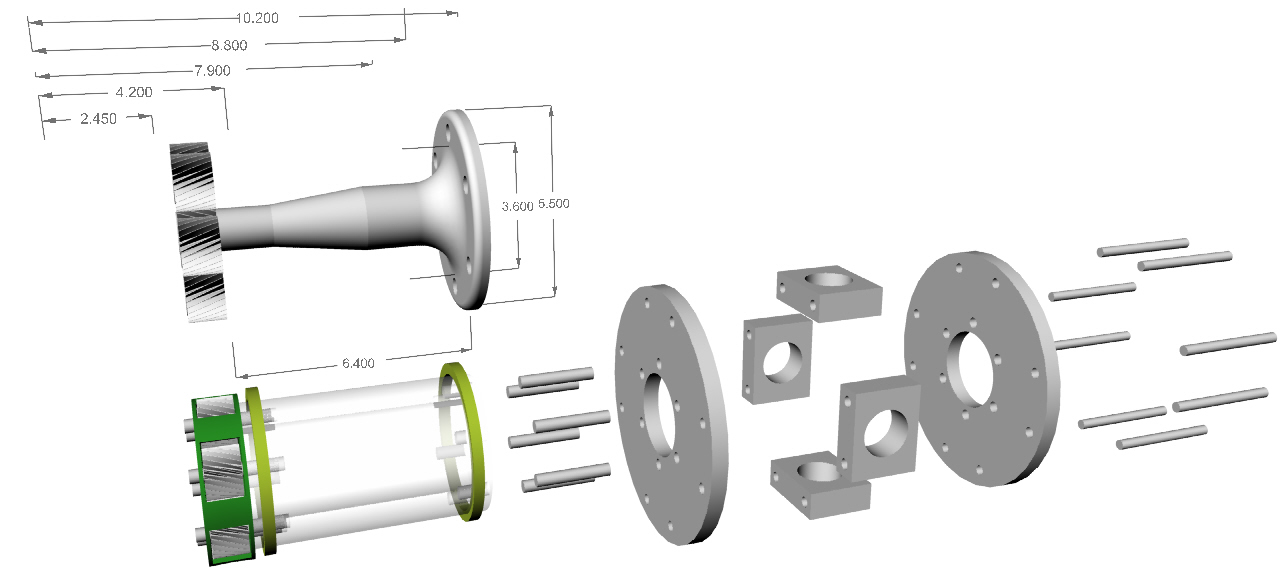
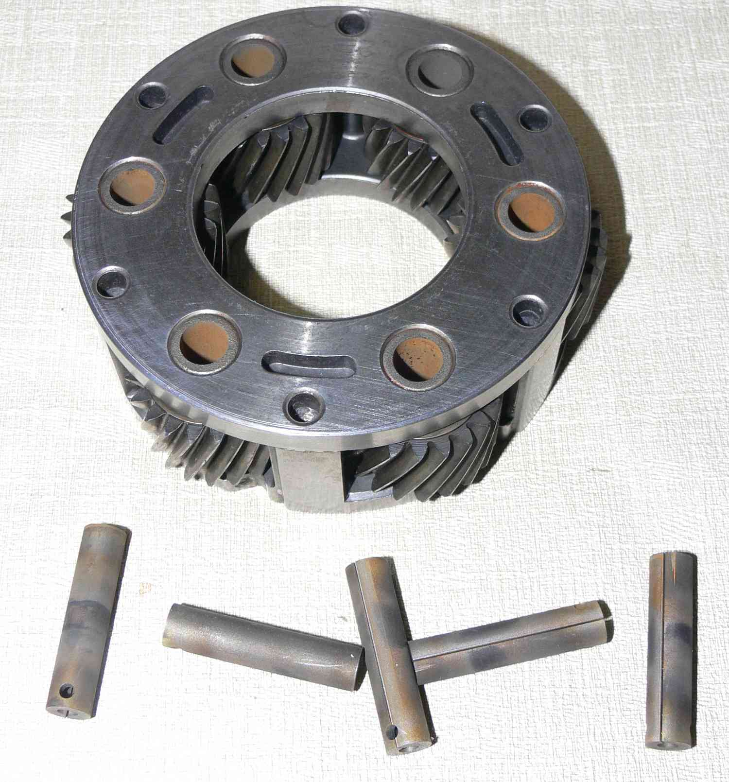
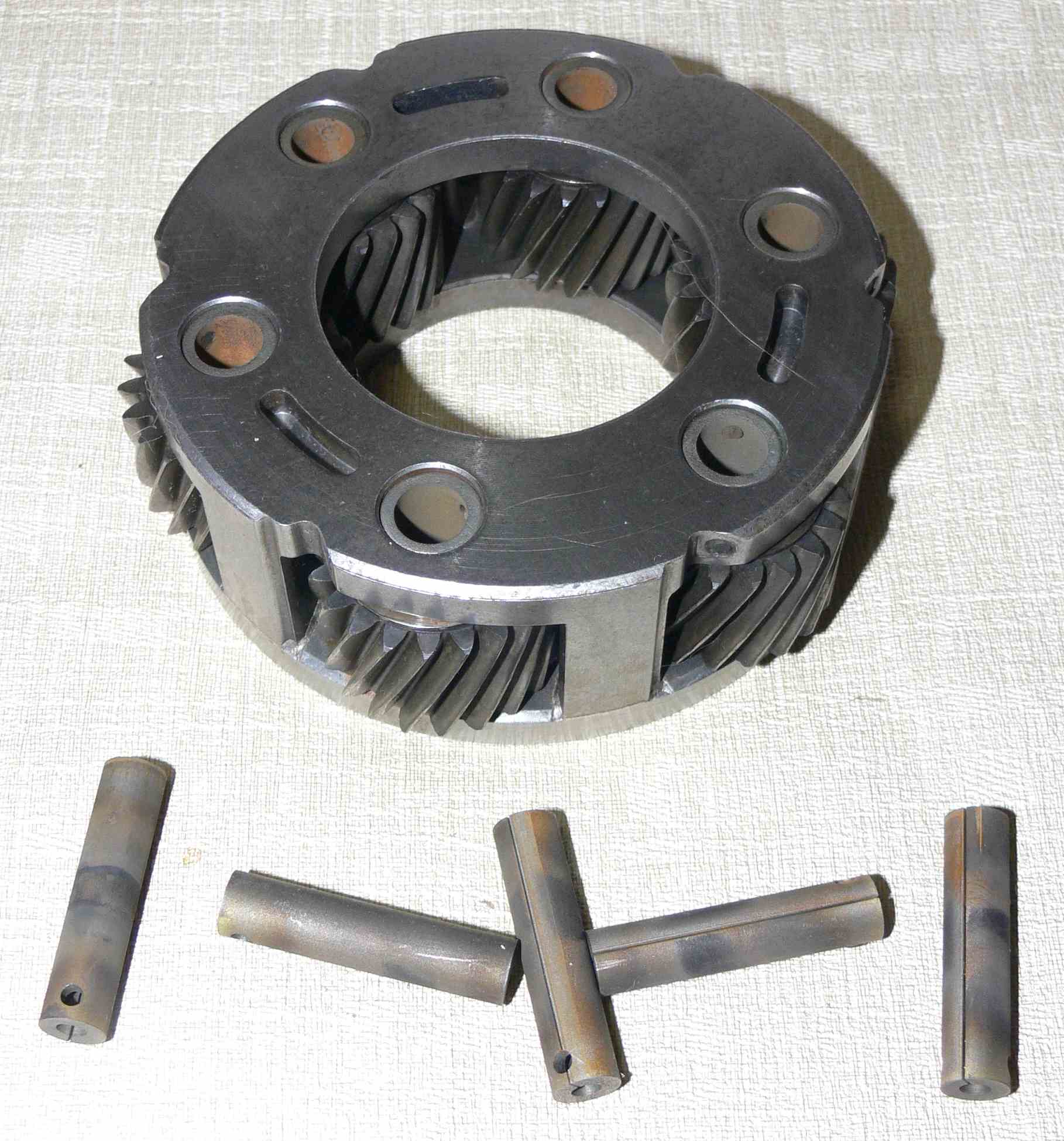
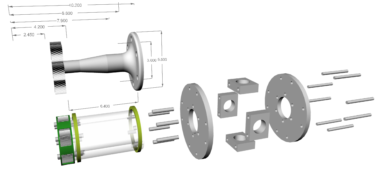
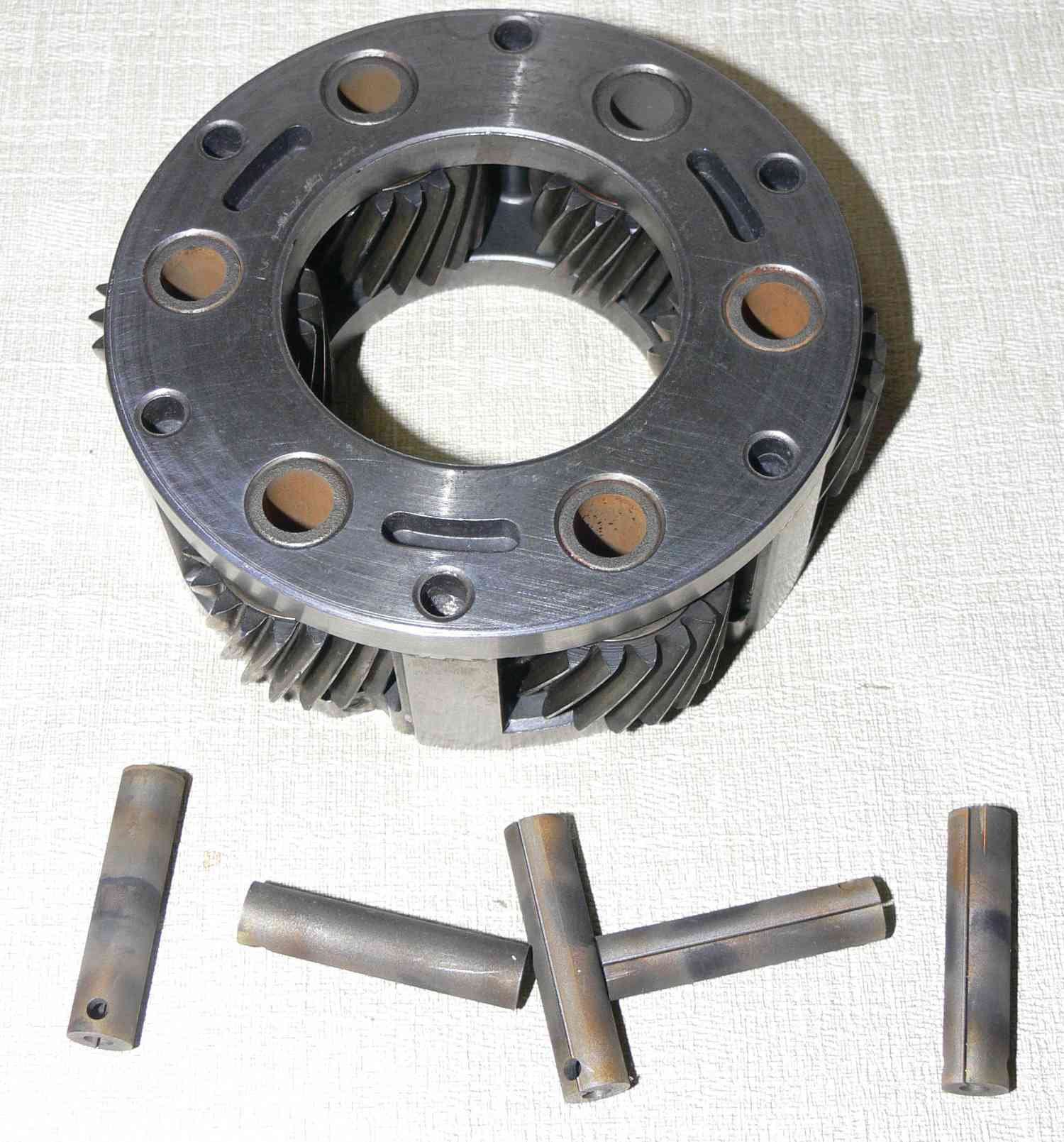
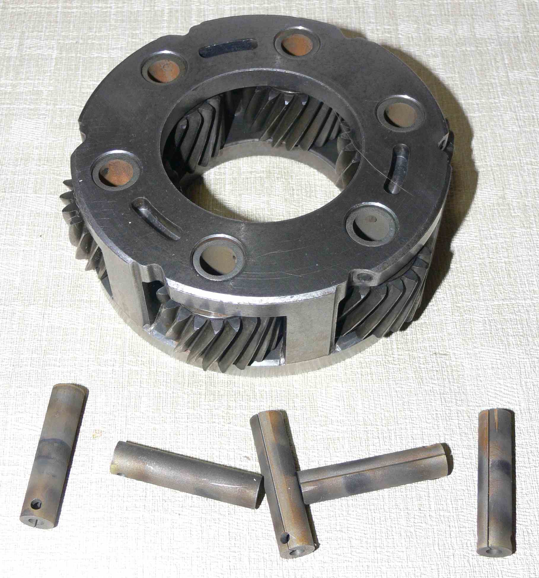
Got the gears for my new super simple gear box
with the four inch diameter aluminum prop shaft.
This does away with half a dozen parts and the need
to heat treat and grind a steel prop shaft.
This is the back Ford planet set with steel planet
carrier. Only about 7.5 pounds.
This will allow the p-port rotary engine to rev to about 9,000
for take off making close to 300 HP. Since Dave Leonard
went 230 MPH with his turbo rotary RV6 at Reno last week
my rotary RV4 ought to go about 240 MPH once I get the carbon
tail done.
It will be a while before I need it so I'll slowly gather
all the other needed parts together.
It will need a custom input shaft due to the large internal diameter
of the sun gear. I am not comfortable with a sleeve.
In effect the use of the stock planet carrier straddles the planet
shafts.
I will have the current 1/2 inch planet shafts EDM-ed out to 3/8th while
they are still in the planet carrier. That way we will keep the stock
finish and hardness.
Six 3/8th inch diameter bolts on a 3.25" BC are over kill anyway.
There is room for six 1/4 inch dowel pins as well. The holes are
already in the planet carrier for those. I am not worried :)
BTW the planet carrier is not steel. Probably sintered powdered iron
alloy. We found that out today when we machined the teeth off.
John Lynch turned me on to high fatigue limit 7075 T73 for the prop
shaft.
40K fatigue limit. The tensile is a bit down from regular 7075 T6.
He claims it is at least twice as good as 6061 T6.
He also says to chromic acid anodize. The one inch wall is way
over kill so I am thinking of machining it down where possible
to 1/2 inch to save a bit of weight.
Here is a good 7075 source. Sunshine Metals in Orange County
or Future Alloys in the San Fernando valley 818 701 1144
We used John's lathe today. He builds a lot of stuff for F16's.
He also did the 2nd landing gear design and build on the NXT.
Flying straight and level there is no radial load on the thin section
bearings with a planetary unlike a spur gear transmission.
This is so simple I should have figured it out years ago.
I had to get over my prejudice for using aluminum for a prop
shaft. Basically all it is; is a simple spacer between the planet
carrier and Warp-Drive/Sensenich type prop flange.
Sensenich is now making 50 HP blades for O-320 RV's.
This a a comparison with Tracy's box.
BTW rumor has it the stock Sensenich two blade hub cracks.
Paul Lamar
Good morning Paul,
You are up early. It must be before 4AM there.
I have sleep problem and then it is almost time to get going for work.
Which bearing do you have in mind? To me the one to use would be the
71822
CD/HCP4 as it has the highest load and fatigue ratings. Granted 1 lb each
but
a bit of weight with higher load and fatigue tolerance might be a good
trade.
Dale Davies
They are all pretty much overkill.
Paul Lamar
I found a source for the thin section bearings. Apparently these are
silicon nitride
balls so they are over kill for our purposes but are top quality. These
are good to 1000 F. I am not sure the seals would live at that temp
however.
Probably not.
BTW Tracy's front ball bearing is also sealed in case you were wondering.
You will need 2.
BTW this gear box design will work with the front planet and yield 2.85:1
for those that just want to cruise.
These bearings are made in China. Unfortunately almost everything
is now a days.
More info. Try getting them direct to save money.
Paul Lamar
I would like a heads up when you area ready to have your planet pins
lazed,
I will get my 2.85 planet to you. Similarly, I will need the 7075 T73
material for the tube shaft. If you would like me to get the stuff and
send
you the length you need out of my order, we'll arrange it. I can easily
cut
it to your length on my chop saw. Don't know the cost yet. I am ready to
get
all this stuff including the bearings. If the 100x125x13 bearings are our
best option, I'll order those too. Two per shaft I presume.
I received the Creavey seals today. These things are really slick. I did
not
expect them to have a see through teflon coating.
Supposed to rain tomorrow, so I'll pay my favorite trans shop a visit and
ask about a pilot shaft with a 1.5" dia at the back end, and about an
accompanying disc center for the damper.
Ed Carver
Great Ed. This box is going to be the cat's meow.
It will be much lower cost too.
I will have planet carrier back by Thursday. It is in
the EDM shop right now. If you want yours done ship it to me
and I will put it in the EDM shop for you if mine works.
I'll know more on Thursday.
I need to do a bit more checking on the bearings. We may
be able to use steel balls and cut the $89 each price.
Another advantage of this design is it does away with the output shaft
spline to the planet carrier. That is another source of backlash in
Tracy's box.
We may even be able to lower the chatter RPM because of it.
I intend using the bell housing you got for me. I am going to use
something like this to mount it in the bell housing. It will be a very
cosmetic looking device. Something I cannot say about the current
boxes. IMHO under the cowl cosmetics are extremely important
when it comes to the acceptance of the rotary. It cannot look
like something you made with a hack saw, drill press and a
large hammer :)
In your pusher case I think you might benefit from a longer box
so you will need a longer input shaft. I am stuck with 14.5" over
all from iron to prop flange. No way do I have enough time
to build a new cowl so I will need a stock length input shaft.
Paul Lamar
I would'nt mind paying the $90 each for a sealed bearing that would last.
According to the spec, they are good for nearly twice our max speed, even
more with gear lube which requires a sump.
Having a really clean forged housing would be nice. No idea the cost. All
I
know about prop shaft length is that the current design is what is used,
as
shown in Buly's setup. I did read about possibility of setting the prop
back
further, don't know how to determine how much further.
I will try to get my planet sent tomorrow to your beach address. Did you
cut the output extension off first?
Ed Carver
I stopped in at a couple transmission shops to look at input shafts. One
shop had hundreds of short input shafts, they handed me a caliper and
told
me to go look on their shelves.
There are a few with our preferred 1.5" dimension, but have a minimum 3.5
inches from where the 1.5 ends, to where the splines begin. That is a
couple
inches longer than the current design. The spline is approx. 1.1" 10
Another possibility is using a 3rd member pinion shaft. The same shop has
as
many of those as they have input shafts. The pinion shafts all have a
spline
within an inch of the 1.5 dimension, and a threaded end that can be
ground
down for pilot use. Usually they can be fitted with a flange for mounting
our adapter plate.
Ed Carver
Take some pictures Ed.
Here is what the inside of a clutch disk looks like.
It could be used as is but Ken Welter has destroyed a few.
Early Ross boxes used them as is. I would take them apart
and tig weld the female spline part to 4130 sheet.
The female splines are square cut so it would be rather easy to
make custom splined input shafts Larry can do that using a straight tooth
woodruff key slotting cutter. The disk I have has .175 wide slots. About
11/64th as key cutters go. There are only ten splines.
Is that doable Larry?
Also this is the six pinion front planet carrier that gives 2.85:1.
The output female spline is still there and needs to be cut off.
The pinion shafts are smaller in diameter (.4375) so only a 5/16 (.3125)
bolt
will work. However there are six 1/4 inch diameter holes for dowel pins
if necessary.
That would add .29 square inches to the shear area taking
about 14,500 pounds to shear them off at a conservative 50,000 psi
max stress for steel. Probably not needed.
The torque load at 600 foot pounds prop torque is 7200 inch pounds so
in theory the shear load is only 2400 pounds at a 3 inch bolt circle.
IMHO easily taken by six 5/16th bolts that have a total shear area of
.46 square inches. At 50,000 psi that is a max shear load of 23,000
pounds.
IMHO all and all a rather conservative design.
Check my arithmetic and numbers.
Paul Lamar
I have welded female splined disc centers the way you are suggesting. and
eliminated the springs to make solid discs by welding together the spring
rectangles.
It looks to me like the extra holes in the planet are for oil. I guess
new
pins could be installed through them if we lazed them together with the
pinion shafts. it just looks very close to the pinions. The pinion shafts
measure .417 on the planet I have.
The input shafts I saw today had square splines. Is that a ford thing? If
we
can live with the extra 2.5 inches or so in length, then these shafts
will
work. In my case probably no problem; your RV needs something shorter,
and
these shafts can't be that short due to the depth of the clutch assembly.
I measure about 4" from the back of the bell to the back of the female
splines of the modified forward drum. This dimension includes our 1"
damper
on top of the counter balance. The square splined input shafts should
work
fine for me since there is extra length on the shaft splines. All I need
to
do is have the pilot reduced to the RX dia., and of course, turn the big
end
down to our sun gear id.
Do you want some dimensions for an apparently adequate third member
pinion
shaft? They will probably let me photo one.
Next up for me is purchasing the 4.125"od 7075 T73 for the shaft, and
also
the material for the housing. I just need dimensions for both materials.
My
ring gear is roughly 5" dia
Ed Carver
.417 Yes not .4375 My mistake.
If you use the 100 mm (.3937 inch ID) bearings the shaft can be 4 inches
OD.
I don't think you will be able to buy 4.125" OD 7075 T73 shaft material.
I could be wrong.
The OD of the bearings is 125 MM or .492 so you will need at least 3/4
wall maybe 1 inch wall. 3/4 wall 6" OD tubing would be 4.5inch ID.
For the housing look for 6 inch OD 3/4 wall or 1 inch wall aluminum
tubing.
Or 6 inch aluminum bar stock. We have a shop at SZP that can quickly bore
really big
holes in really big bar stock with a really big and powerful lathe :)
Paul Lamar
That is simple enough, one 10" long 6"od 3/4 wall tube for the full
length
of the housing. The opening in the back of the bell is approx 6.2"
Do you thnk the 4" od will give us enough step to keep the 100mm bearing
in
place?
Ed Carver
Yes.
Paul Lamar
-- Flange type joints are a friction drive. The bolts are there to
provide the clamping pressure, they should see little or no shear loads.
One of the problems (there are some) with the aircooled VW is the dowel
pins and the single big nut to hold the flywheel on. Getting enough
clamping pressure is the problem. Doubling the no. of pins helps and
some
companies do wedge mating, a matching taper on the crank and flywheel to
increase friction and area. The shear strength calcs should be
conservative as long as there is enough surface area in contact.
Murry I Rozansky
Hi Murry!
Hope to see you at Whiteman this month, been too busy the past couple
to get
there.
I'm not certain to what you are referring with "flange type joints".
Is it
the modified forward drum with the rivets? Or fastening mating surfaces
between the planet housing and the new 4 inch prop shaft? The 13b has a
tapered crank with a big nut holding the balancer/flywheel.
Ed Carver
Paul,
Is not that size of 125mm equal to 4.92"? I have looked at a
couple of times, thinking there was something wrong with the numbers, I
have not done a conversion but 125mm is aprox. 5"long!
John Burey
Yes. One inch is 25.4 mm.
Yes! The bearing OD is about 5 inches! That is what is so spectacular
about this gear box design. This is a classic example of how a major
technical
improvement in one field can affect a radical improvement in another.
The silicon nitride balls can allow this large OD thin section bearing to
rotate at high speeds with tiny balls that are really zinging along.
This is not your grandfather's PSRU let alone your father's :)
Despite the bearing cost of $90 each this is a major reduction in
the over all cost of a PSRU.
The use of the thin section bearing allows a drastic reduction in the
torsional stress applied to the prop shaft by doubling it's diameter. This
in turn
allows the use of 7075 T73 aluminum for prop shaft material. That in turn
does
away with some very expensive machining, heat treating and grinding
required of steel prop shafts with large diameter flanges.
In some cases forgings would not be required.
There is also a possibility that silicon nitride roller bearings can be
used
as rotor bearings allowing low cost charge cooled and lubricated
Wankel engines, like the AIXRO, to rev higher and make more continuous HP.
Paul Lamar
Paul
How are you going to space the planet pins flush with the carrier? I also
recommend using a washer under the bolt head for belt-and-suspenders
to hold the planet carrier to the shaft. Loctite and wire secure the
bolts?
Are you going to include the torque meter? Design is looking really good!
Dan F
Space the planet pins?
The torque meter is so simple someone can add it if they
wish. Nobody is going into production on this as far as I know.
It is DIY.
Paul Lamar
Paul,
If you calculate the shear stress it is way over kill.
==============================**============================
Shear Stress in the Shaft
http://www.engineeringtoolbox.**com/torsion-shafts-d_947.html<
http://www.engineeringtoolbox.com/torsion-shafts-d_947.html
When a shaft is subjected to a torque or twisting, a shearing stress is
produced in the shaft. The shear stress varies from zero in the axis to a
maximum at the outside surface of the shaft.
The shear stress in a solid circular shaft in a given position can be
expressed as:
? = T r / Ip (1)
where
? = shear stress (MPa, psi)
T = twisting moment (Nmm, in lb)
r = distance from center to stressed surface in the given position (mm,
in)
Ip = "polar moment of inertia" of cross section (mm4, in4)
The "polar moment of inertia" is a measure of an object's ability to
resist torsion.
==============================**==============================**
========================
Polar moment of inertia of a circular solid shaft can be expressed as
Ip = ? R4/2 = ? D4/32 (3)
where
D = shaft outside diameter (mm, in)
Polar moment of inertia of a circular hollow shaft can be expressed as
Ip = ? (D4 - d4) /32 (3b)
where
d = shaft inside diameter (mm, in)
==============================**============================
T = 7200 inch pounds or 600 foot pounds. 3 times engine torque.
D = 4 inches.
r is 2 inches.
d = 2 inches.
-=============================**====================
Run these number and let me know what you come up with
in terms of shear stress. I think you will find these numbers
are extremely low.
As far as the tension load on the bolts is concerned 7075 T73
has a yield stress of 80,000 psi.
Assume for the moment the bending load on the prop shaft due to
gyro reaction for a 25 pound prop at a pitch or yaw rate of one radian
per second is about 300 foot pounds or 3600 inch pounds. Assume for the
moment there are only two bolts holding the aluminum prop flange onto the
aluminum prop shaft. At a bolt circle of 3.5 inches the load on the bolt
is 1028 pounds. Assume the bolt is made from 7075 T73 aluminum and it is
3/8th inch in diameter or .375". The area of the bolt is then .44 square
inches. (pi X r squared) Therefor the max TENSILE LOAD the bolt will
resist
is 80,000 psi times .44 square inches or 35,343 pounds.
That is a safety factor of 35!!!. There are a minimum of six bolts.
There is room for 12 3/8th bolts if you wish to be more conservative.
If you go up in bolt diameter to .5 inch the stress on the aluminum goes
way down. Since the wall on the prop shaft tube is 1 inch a .5 inch bolt
is easily accommodated. I suggest titanium 1/2 inch bolts to save weight.
As I said this is a major break through in low cost PSRU design.
Paul Lamar
How does one calculate cyclic fatigue loading?
I could look it up, but I'm not where I can do it at the moment..
Matt-
If it bends back and fourth you use a lower stress limit.
For 7075 T73 it is about 40,000 psi.
For heat treated 4130 it is about 65,000 psi
Mild steel is as low as 14,000 psi.
Most aluminum has no fatigue limit. Sooner or later
it will crack.
Usually it takes several million cycles to test for this.
It is possible to use long tension bolts in this design that
go all the way from the planet carrier to the prop flange.
Much like the 13B tension bolts.
That way no aluminum need be involved. The prop flange itself
can be a simple 4130 disk. This would make it ridiculously over
designed.
Paul Lamar
Paul,
Torsional stress of the bolts and Al pipe/shaft are not the issue. Matt
stated it better than me. The bending moment between the prop flange and
pipe/ shaft concerns me. I've been down this road before with wind
generators and have seen Al. parts on the tail boom that were relatively
unloaded, crack once the unit was in the field for years. We KNEW it was
over-designed. We were wrong. A combination of environmentalissues, salt
air, water dirt etc. combine with (perhaps) an occlusion in the cast metal
created stress cracks. After
witnessing this phenomena several more time the tail was beefed up.
Cyclic stress is a nothing to laugh at. You are talking about material
strength, I'm talking
about toughness. I good quality forged steel has a grain and this is what
makes it tough. For toughness bamboo would be a better choice:) Ah! but
you know all this. Since you're on the bleeding edge of technology can I
assume you are going to test the unit hundreds of hours before flying with
it or recommending the design for others to fly with?
The long bolt design sounds interesting. What are the strengths and
weaknesses of that design approach?
http://www.epi-eng.com/**mechanical_engineering_basics/**
fatigue_in_metals.htm#est<
http://www.epi-eng.com/mechanical_engineering_basics/fatigue_in_metals.htm#est
Doug in Japan
I am not laughing at cyclical stress I am very familiar with the fatigue
limit. Why do you think I go on and on about piston engines. Did you
know some aircraft piston engines use aluminum rods?
I calculated the cyclical stress and it is ridiculously low. I am not
worried
at all. We are talking 1 inch wall tubing and 1/2 inch thick
aluminm plate. That is a far cry from your wind turbines. If you are
concerned run
tension bolts all the way and use a 4130 prop flange. Better yet
don't build one.
They can make their own judgments. I am not selling anything. Don't try
this at home. I am a professional :) Do it the old way if you wish.
IMHO it is a major break through. It is normal for people to resist
new ideas.
Paul Lamar
Hi Paul,
Always look for the fatal flaw.
I remember a planetary gearbox being designed and developed by Norton for
a single Rotary Engine some 25 odd years ago, for I think drone, and a well
known gear consultant was involved of World renown (Nationality Withheld),
So confident that the design was good to go, the engine was shipped to USA
for test cell running by the co developer, In the test cell with the prop
now fitted the Gearbox failed on the starter motor, lasted about 3 starter
presses, the second improved one ( 2 months later) lasted about 7 minutes
of
running.
I only make this point, in engineering my old Boss Doug Hele used to say
expect the unexpected.
I remember Long housing through bolts, from over 30 years ago we learnt
that
bolts on the twin engine Rotary would last much longer if we inserted
silicone sealant into the housing stud hole by the centre plate, this
stopped a resonance that was at the time unexpected but caused premature
failure of the studs around 3 threads in, rolled form threads and full
fillet radiuses and polished and shot peened thread was also tried.
Bob
UK
That is very common. Prop gear boxes chatter. Fact of life.
The prop is a huge flywheel. At some RPM you will get chatter.
When you taxi a 2.17:1 gear box make sure you taxi at over 1800 RPM.
Use the brakes if necessary. Less of a problem with a 2.85:1 gear box.
Tracy never noticed this because he lives on a grass strip.
We know about the tension bolt problem as there is clearance between
the tension bolt and the rotor housings allowing the bolt to vibrate
like a violin string. Not what I am talking about for the new PSRU.
The bolts go through a drilled clearance hole in what amounts to
a large 4 inch diameter aluminum spacer used as a prop shaft.
Paul Lamar
I don't recall which alloy I should request for the 6" housing. I have found
a couple sources for the 7075 T73 in bar form.
We are really just starting to realize the potential for this design. Once
we establish which is the best way to hold the planet on the tube/spacer, it
would then be easy to create a carbon version, or one out of steel. Many
different designs can be applied to either end of the tube/spacer, as well
the length can easily be changed.
In my pusher, the thrust will first land on the radial bearing that is
between the planet and the ring gear hub. The ring will be fastened to the
housing around it's perimeter and the hub to the front of the housing. We
are just turning around the parts compared to the way it is in the dragster
axel design. then it's just a matter of getting the thrust bearings set up
correctly between the sun gear and the housing cover .
We hav'nt discussed sealing yet, or lubrication, but it does'nt look to
difficult with only two bearing locations.
I hope to have material in hand by mid week.
Ed Carver
If you don't mind get me an extra 14 inches of the four inch diameter 7075 T73
Ed and I will pay you back when I get back from up north.
Hold off on the silicon nitride thin section bearings as I think
Henry Nee can get us a better price direct from China in a few weeks.
If the price is low enough I might double up just to be on the
conservative side.
BTW if you get your planet carrier EDM'ed make sure they drop it
in a can of oil as soon as it is removed from the EDM machine.
They won't know that without being told.
The EDM machine does a great job of displacing the last traces of oil in
the needle bearings with pure water :) It will rust within a matter
of minutes. One MUST displace that water and air with oil instantaneously
if not sooner. In case you don't already know EDM is done under water.
I had another idea on the Warp drive/Sensenich prop flange.
.025" thick 4130 sheet epoxy bonded on either side of 1/2 inch anodized
aluminum. That would be a good damper for any weird vibration
modes. There are a lot of bolts holding them in contact with each other
as well of course.
BTW note the cube term in the torque equation.
2 cubed is eight.... 4 cubed is 64. EIGHT TIMES STRONGER!! All other things
being equal.
Paul Lamar
--
The Rotary Engine NewsLetter. Powered by Linux.
ACRE NL web site.
http://www.rotaryeng.net
Youtube key word PaulLamar2
Copyright 1998-2011 All world wide rights reserved.