a very good and interesting article on props. His props performed as
advertised.
http://www.eaa.org/experimenter/articles/2009-02_elippse.asp
DON'T IGNORE
chris smale
Chris,thanks for the post.I've been meaning to refer this article in the
Experimenter to the group,since I think that Paul Lipps' work is
ground-breaking in the field of propeller theory,which has always been held
as a "dark science" and a new way of designing and applying his
ideas to the aircraft engines in the HP range that we consider.
Paul and the rest of the group:What do you think about this new approach to
propeller design and efficiency,and do you see any particular benefits to
its applications to rotary engine propulsion?
Dave Young
Old Message from 2006
------------------------------------------------------------------------------------------
The pitch of my old wood propeller which I am retiring is given in inches,
while my new Warp Drive uses degrees to set pitch. No reference to inches.
What is the relationship between the two methods of measurement? Can you
direct me to reference material (for the layman)?
Yvon
There is only one true measure of the pitch of a propeller as
installed on a particular airplane! That is the effective pitch, which
is the amount the airplane goes forward, in inches per revolution, in
horizontal flight. It's an easy formula: TAS, mph, times 1056 divided by
rpm.
At most airspeeds and rpm, in level flight, the effective pitch
of my strange prop is 76". It has to be taken in level flight since the
prop load is different climbing or descending. If your prop's effective
pitch changes much at different speeds and rpm, its twist and/or chord
distribution is not optimum. As you can see from the previously shown
helix-angle tables, most fixed-pitch props have insufficient twist as
compared to the tables, and actually generate reverse thrust in the root
area which, besides considerably reducing the prop's efficiency, blocks
the cooling airflow, requiring larger cooling inlets, thus more drag.
I've heard many stories about how, even though someone has given his
plane more throttle and rpm, the speed didn't change. If the rpm
increased and the speed didn't increase proportionally, then the prop is
on the downward-slope of its efficiency curve. So a 1% rpm increase
should result from 1% more speed, not the other way around*. Your
speed increases from increased hp, and your prop now turns faster! Now
if you have a 100 mph TAS plane and you advance the throttle to where
your rpm goes from 3000 to 3030, your speed should increase to 101 mph;
that's pretty hard to see! However, if your rpm increases, say, 5%, from
3000 to 3150, then you should see 105 mph TAS. If not, your prop has
insufficient twist and you are generating reverse thrust inboard which
works against increased thrust outboard.
*I modified the tips of my friend's prop on his Lancair to reduce tip
drag. The speed increased from 215 mph at 2600 rpm to 219 mph at 2650
rpm. To increase speed that much required (219/215)^3, 5.7% more power.
But 2650 rpm/2600 rpm is only 1.9% more rpm, so only 1.9% more power.
And the speed increase was 1.9%. So, 1.9% more speed, 1.9% more rpm! The
speed increase was due to the prop's increased efficiency due to much
less tip drag!
Paul [Lipps]
Thanks Paul! Very very informative.
Paul Lamar ...No rotor no motor.
The Rotary Engine NewsLetter. Powered by Linux.
ACRE NL web site.
http://www.rotaryeng.net
Copyright 1998-2006 All world wide rights reserved.
===================================================================================
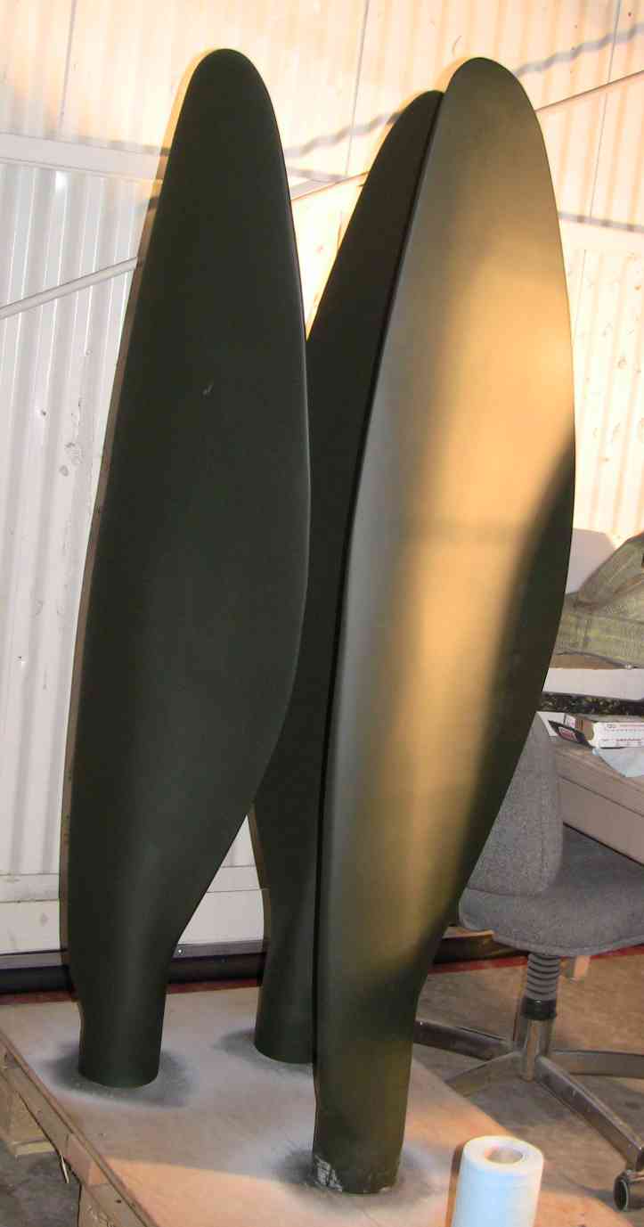
Not a new idea.
Here are some old pictures.
Paul Lipps's theory on prop tip drag IMHO are very valid.
The basis for this way of thinking is called "blade element theory".
Google it.
Unfortunately prop blades are also subject to span wise flow due to
centrifugal loads on the air molecules. That is why you see this plan form
on the highly efficient FW190 prop blades. The FW190 radial engine had a geared up
cooling fan that compressed the air around the cylinders. The cylinders in the process
of cooling off added heat to the compressed air which was then ejected out the back
with movable cowl flaps generating some thrust very similar in principle to the P51.
Paul Lamar
--
The Rotary Engine NewsLetter. Powered by Linux.
ACRE NL web site.
http://www.rotaryeng.net
Youtube key word PaulLamar2
Copyright 1998-2011 All world wide rights reserved.