On Tue, Oct 25, 2011 at 4:48 AM, Rotary Engine <
rotaryeng@earthlink.net wrote:
Yes, Paul, using logic chips you can certainly do a lot without resorting
to
programming. On the right was my first "Analog" EFISM with which I flew
with for years using the same Seg 7 display you mentioned using. The
"Analog" EFISM provided Air/Fuel Ratio, Fuel Flow and Total Fuel used.
On the left side of MVC-012F was my first primitive "Digital" EFISM (much
improved board design since then -see EIC_EFISM II Front ...), I went to
digital because the analog board just did not have the flexibility for all
the functions I wanted to add. So the transition to the "Dark -Digital"
side using the Microchip PIC series that you had recommended.
Ed
Edward L. Anderson
Anderson Electronic Enterprises LLC
305 Reefton Road
Weddington, NC 28104
http://www.andersonee.com
http://www.eicommander.com
I did not really like PIC assembly language.
I prefer chips like the 6502 and 68K.
Unfortunately they are almost gone but Megasquirt still uses them.
A good high level language makes that a moot point.
Something some one can actually read like BASIC.... unlike C
now used by Megasquirt :)
I am fond of ZBasic and Atmel chips now due to their very fast
compiled Basic. Makes programming ten or 20 times faster than
assembly and you can teach your kindergarten great grand child
how to program. :)
http://www.zbasic.net/
They still have a bit of problem with hardware interrupts.
I started using latched hardware interrupts in the early 1970's with
the 6502 Superkim board I designed and manufactured.
The computer chip world still has not implemented latched
hardware interrupts. It will probably happen after I die :)
Here is a rudimentary EFI timed injection system written in ZBasic.
Sub Main()
Call PutPin(12, zxOutputLow) ' pin 12 CAS 1 will be at logic zero
Call PutPin(13, zxOutputLow) ' pin 13 CAS 2 will be at logic zero
dim x as long
'check and wait for CAS. Polling. Not necessary with hardware int.
'do
for x = 0 to 3000000 'develop only
If (GetPin(12)=1) then
Call rotor1
end if
if (GetPin(13) = 1) then
Call rotor2
end if
'loop
next x 'develop only
end sub 'main
sub rotor1() 'it is 22 degrees BTDC
Call PutPin(14, zxOutputHigh) ' trigger ign rotor1
dim add1 as integer
dim add2 as single
dim add3 as single
add1 = GetADC(82) 'MAP sensor val must be an integer
add2 = CSng(add1)
add3 = add2/10.23
' prepare for 100Hz Fast PWM using channel 2
Call OpenPWM(3, 250.0, zxFastPWM) ' set the pulse width.
Call PWM(3, add3) ' generate PWM with the add3 value.
Debug.Print " = " & CStr(add3); 'send it out the USB port to the PC.
Call PutPin(14, zxOutputLow) ' turn off ign trigger
end sub 'rotor1
sub rotor2() 'it is 158 degrees ATDC stub.
'Debug.Print "rotor 2"
End Sub 'rotor2
Paul Lamar
I agree, tried assembly - but, it just took me too long to work out the
code for anything fairly complex - so I found a PIC Pascal Compiler that
does a nice job and has a nice IDE. Been using it ever since the company
put out its first alpha code on it - and get all upgrades free. It
appears
my unorthodox programming method catches bugs that their testers miss and
apparently they figure its worth the price of the compiler upgrades. They
now have one for the 32 bit microchip series - but, just no justification
for me to switch from their 8 bit to the 32 bit to do what I need to have
done.
The company now also have C and Basic compilers - but, no reason for me
to
switch at this stage. Tried C three times and just never found it
lovable.
The PIC is a real bit-banger of a chip and if you get a single bit
incorrect, the entire program may not work, but a lot of capability in my
opinion.
Ed
Ed, when using those multiplexed 4 digit LED's did you notice a drop off
in brightness? Here is a counter kit that uses an Atmel processor to
multiplex the display and act as a counter.
Unfortunately it is limited to 100 counts per second I think.
at 8000 RPM we have
a count rate of 133.333 counts per second one pulse
per rev.
If we look at the 100 teeth on the flywheel the CPS rate
goes up to 13,333 at 8000 RPM.
On your
http://www.andersonee.com/ EFISM what is the update rate
when displaying the RPM? I assume you measure the elapsed time between
ignition events and divide that into a constant.
Example:
2000 RPM is 33.333 CPS or one rev in .03 second.
The computer can measure the time it takes to make
one RPM in seconds.
So to get RPM we need to reverse this process.
1/.03 = 33.333
33.333 X 60 = 2000 RPM.
At 8000 RPM it is 133.3333 CPS (Hertz) or one rev in
.0075 second.
1/.0075 = 133.3333
133.333 times 60 = 8000 RPM.
Is this correct? How many microseconds does it take the PIC to
divide the ignition period into 150?
BTW I have one of your EFISM but I would like a tach that was on view
all the time and not time shared with other parameters.
Paul Lamar
Hi Paul,
My EFISM calculates RPM based on the period between injector pulses since
they are (for the rotary engine) 360 deg apart or once per revolution. I
run the chips at 32 Mhz which gives me a CPU clock internal of 1 usec. The
PIC 18F6722 has its own CCP module which has several configurations you can
select as to what pulse conditions you want to trigger it. At 32 Mhz the
time required for rpm calculation is insignificant compared to the period
between pulses even at 8000 rpm. This is all integer math - no floating
point, because its just not needed when you have a resolution of 1 usec tics
for the period compared to even a 1 Msec period.
The module is set up (in the EFISM) case to measure the period between
pulses in clock cycles. Then this clock cycle count of the rotation period
is turned into an RPM through the following calculations.
//These two calculations are done prior to enter Tach RPM display Loop.
PPR = Pulses per Revolution.
if (Tach_ConfigRPM.Tach_PPR = 0) then //used for sine
wave generators Westach for a PPR of 1/2 or once per 720 deg cycle
Tach_K := 60000000 * 2 //1/2 PPR
else
Tach_K := (60000000 div Tach_ConfigRPM.Tach_PPR); //
1/2 PPR //used for all other PPR values
//The Tach_K calculation is done once in the initialization period of
the EFISM so only the following division is done each pulse interval
RPM_Tach := Tach_K div R_Period; //RPM calculated based
on TACH_K constant, R_Period has the number of clock tics between pulses
the chip module counts the clock ticks between injector pulses and then
adjusts for whatever PPR (Pulse per rev) figure is being used (its 1 for the
rotary and 2 for most 720 cycle piston engines ) and then figures in the
constant 6000000 to turn it into time/rpm. The constant is naturally
dependent on the CPU clock cycles which is dependent on the oscillator freq
which is dependent on the chip - so will vary for other chip frequencies or
different chip types. Remember I do not use a separate TACH input - its all
derived from the injector cycle.
Regarding the 7Seg displays, no I did not notice a drop off in brightness,
but I used a "ganged" set of 4 in one module - rather than an individual 7
seg module for each numeral. Don't know if that would have made a
difference or not.
Regarding the EFISM TACH - for one customer who wanted to use the EFISM as
his primary Tach (which it really was not intended for - the RPM data was
available so I just threw it in). In his case, I moved the rpm from the
display screen you see it on - to the display screen with the air/fuel ratio
bar at the top and fuel flow displayed. The Fuel Used was moved to the
display where the rpm had been displayed. So this gave the customer
air/fuel ratio, fuel flow and RPM on one screen. I also made the rpm Digits
larger to where they filled the display horizontally.
Ed
Thanks Ed.
"So this gave the customer air/fuel ratio, fuel flow and RPM on one screen."
Can you update mine to this configuration? Send a picture of the screen.
BTW what do you think of the Android terminal emulator just uploaded?
Paul Lamar
Henry Nee wrote:
Paul,
Not sure if you are still looking for a separate RPM meter. I found
one in China that operates on 12V supply for about US$10. The maker
claims that it measures the duration of the pulses and convert it to
RPM so it can update pretty fast but did not give me an exact time.
From my readings, it seems that most of those meters operates on two
modes. For lower RPM, they measure the duration between pulses, and
for higher RPM, they measure the number of counts per second or 0.1
second, depending on the accuracy you want.
If you are still thinking about a dedicated RPM meter, it has 0.5" LED
display, and can count up to 9999 RPM.
Add another $10 or so for mail. Let me know.
regards,
Henry
Great Henry. It is worth a try. Send me your mail address by putting
private in the subject box and I will send you the money.
I guess you saw the terminal emulator post for the android.
https://market.android.com/details?id=jackpal.androidterm&hl=en
Here is the other piece of the puzzle for a complete aircraft EFIS android system.
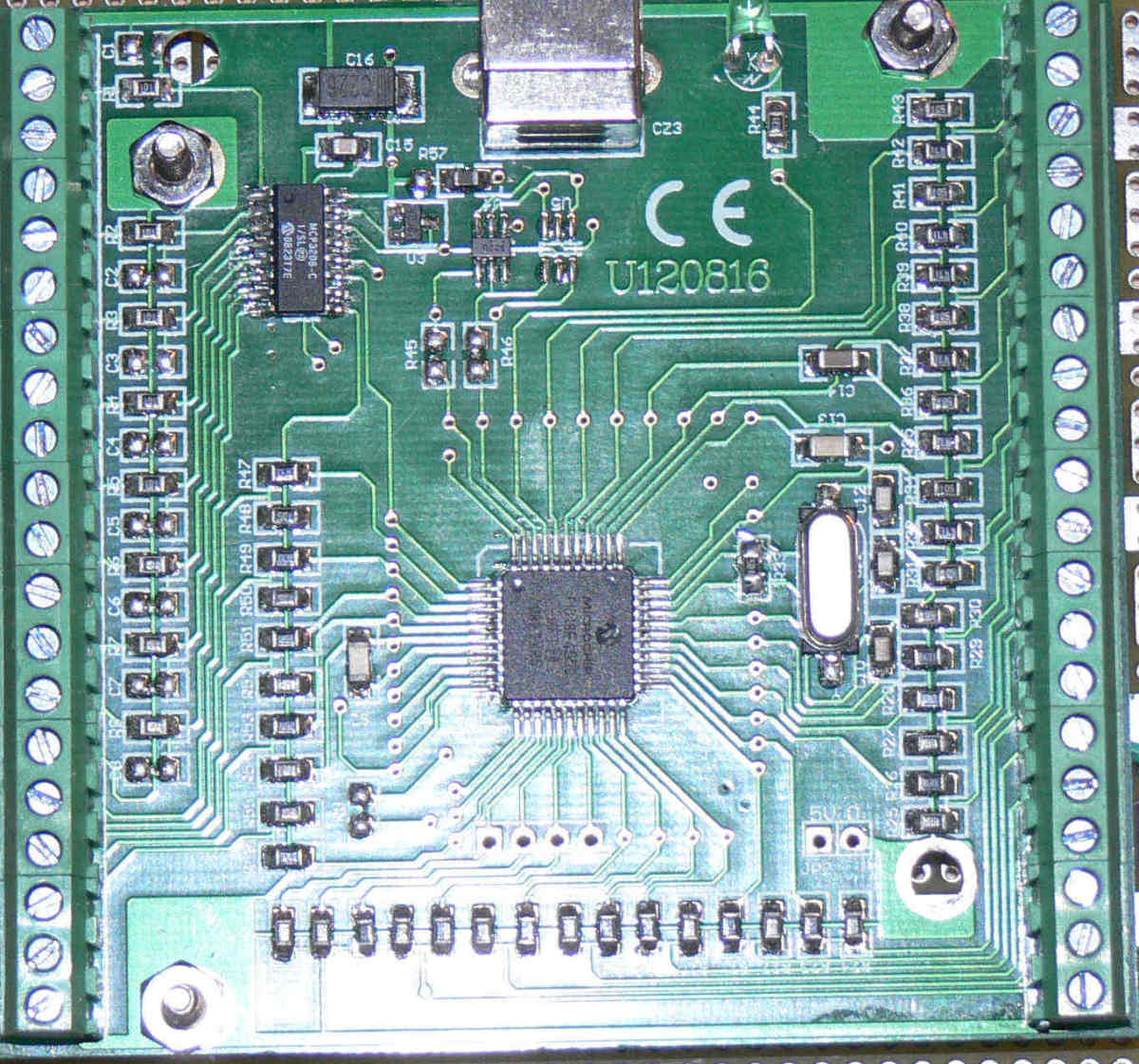
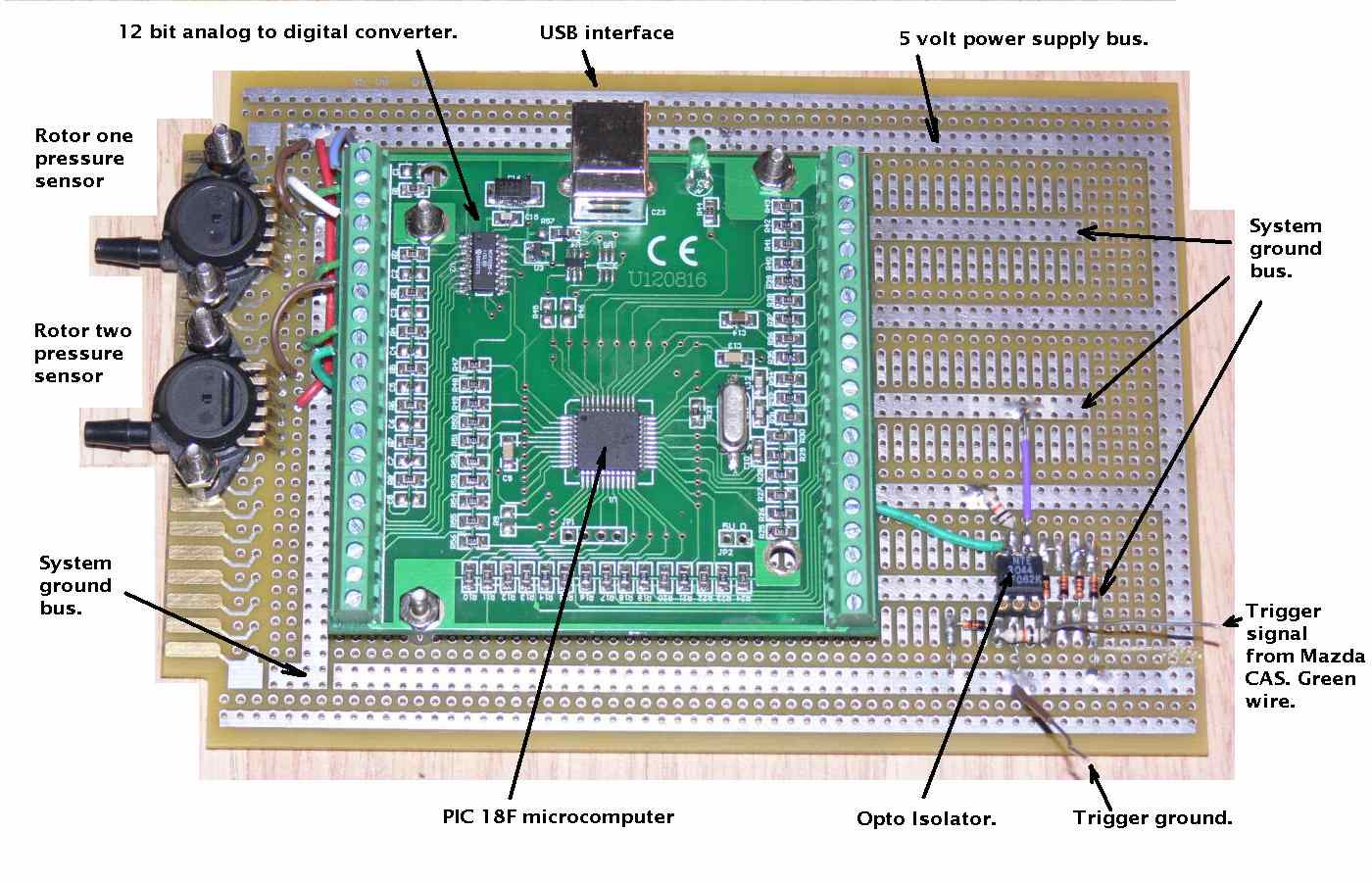
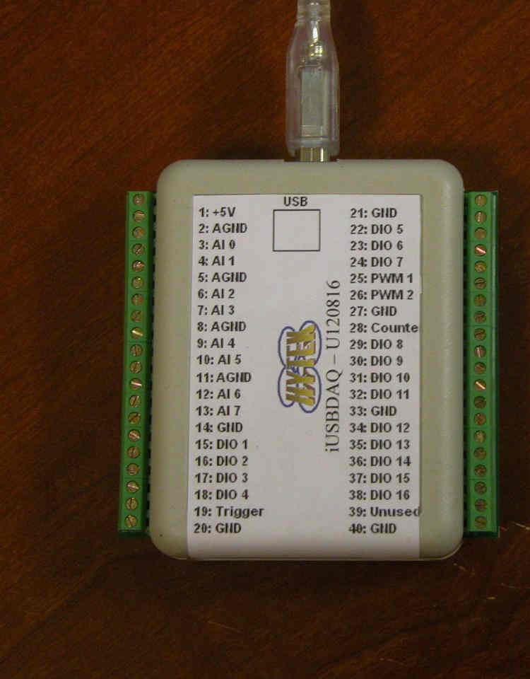
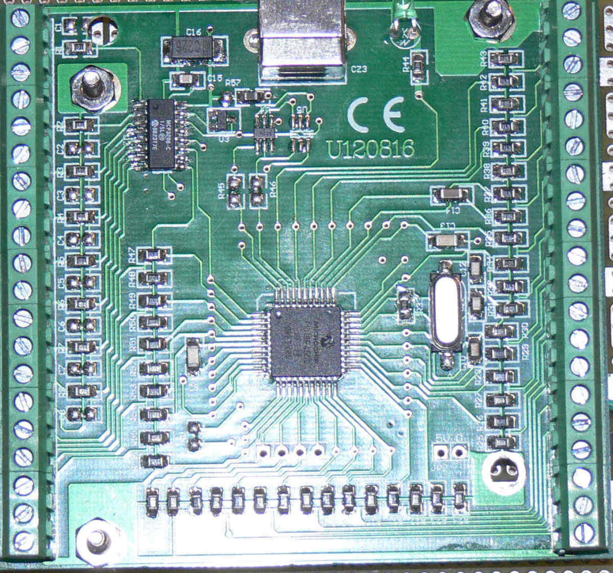
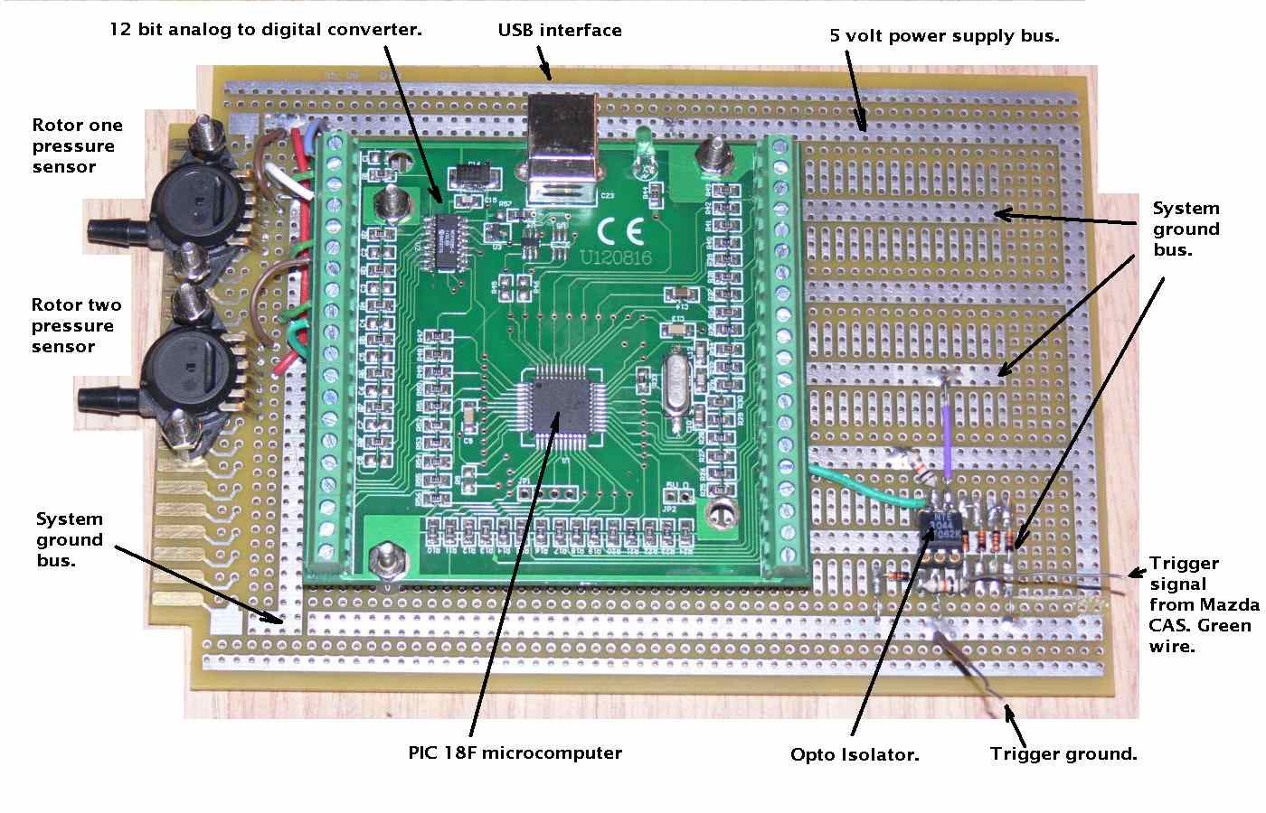
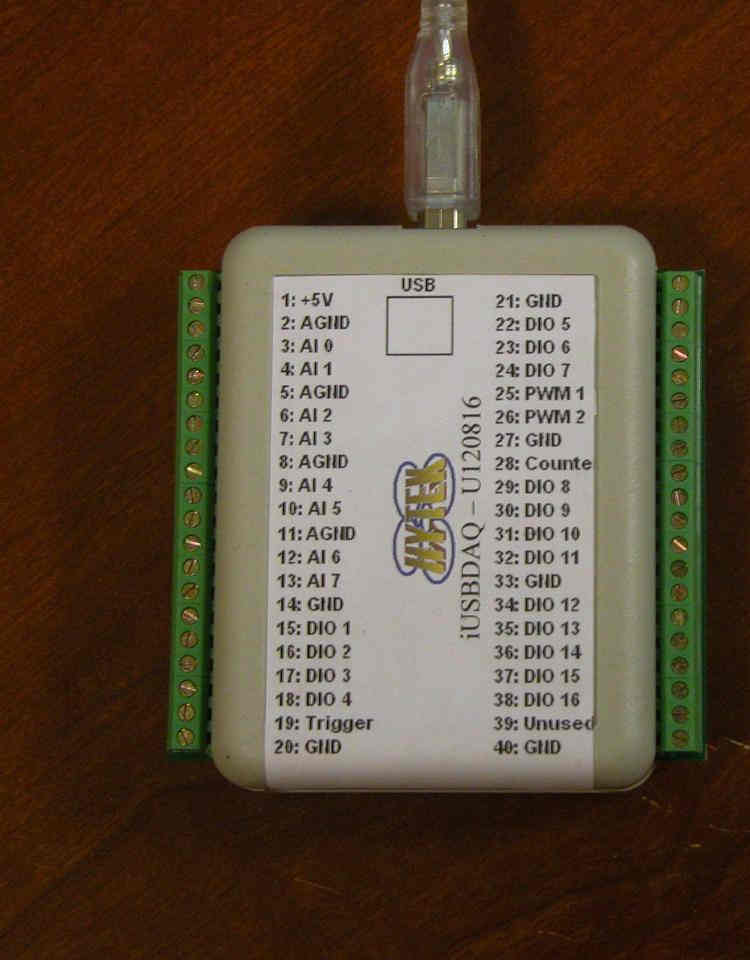
http://www.hytekautomation.com/
About $80
It works great with Windows. Perhaps you can talk them into doing a software version
for the Android.
Paul Lamar
The Rotary Engine NewsLetter. Powered by Linux.
ACRE NL web site.
http://www.rotaryeng.net
Youtube key word PaulLamar2
Copyright 1998-2011 All world wide rights reserved.