Hi Paul,
I've finished my (13mm) thick butterfly throttles and I'm trying to decide if an
over the top variable induction pipe (runner) system will have any merit.
Near sealevel yes, but what about up high?
Does air pressure within the airbox affect the optimum length?
Doug in Japan
Frequency = speed-of-sound/wavelength
An alteration in either speed or wavelength will result in an alteration of the natural frequency.
You can calculate it from this chart.
Why 13 MM ?
Paul Lamar
Paul,
Thanks. I recently found out that the total volume of the air box and ducts,
filter etc. is important. Especially for a turbo charged engine. Too little
and the air resistance goes up so the engine is starved. Too much and the
response time is lowered, or the engine bogs. For aircraft I would imagine
it is better to err on the side of being to big.
Here is a handy calculator I discovered for the speed of sound calculations.
http://www.sengpielaudio.com/calculator-waves.htm For simpler
calculation based on temp. only try here.
http://www.sengpielaudio.com/calculator-speedsound.htm I used this to
determine that at cooler temperatures (up high) the tuned length
As for why the 13mm thick throttle, the short answer is that number is the
minimal thickness that would work without throttle plate interference. The
throttle plate as designed is actually slightly elliptical. Edges are
slightly beveled to reduce air resistance. I'll fine tune the shape once I
put it on the flow bench. Long answer: Having the throttle directly on the
housing and having the throttle plate swing down inside the inner sleeve is
about as close to the intake port as I could get it in the intake size I
wanted. I explored several variations of slide throttles but was unhappy
with the large amount of real estate it required.
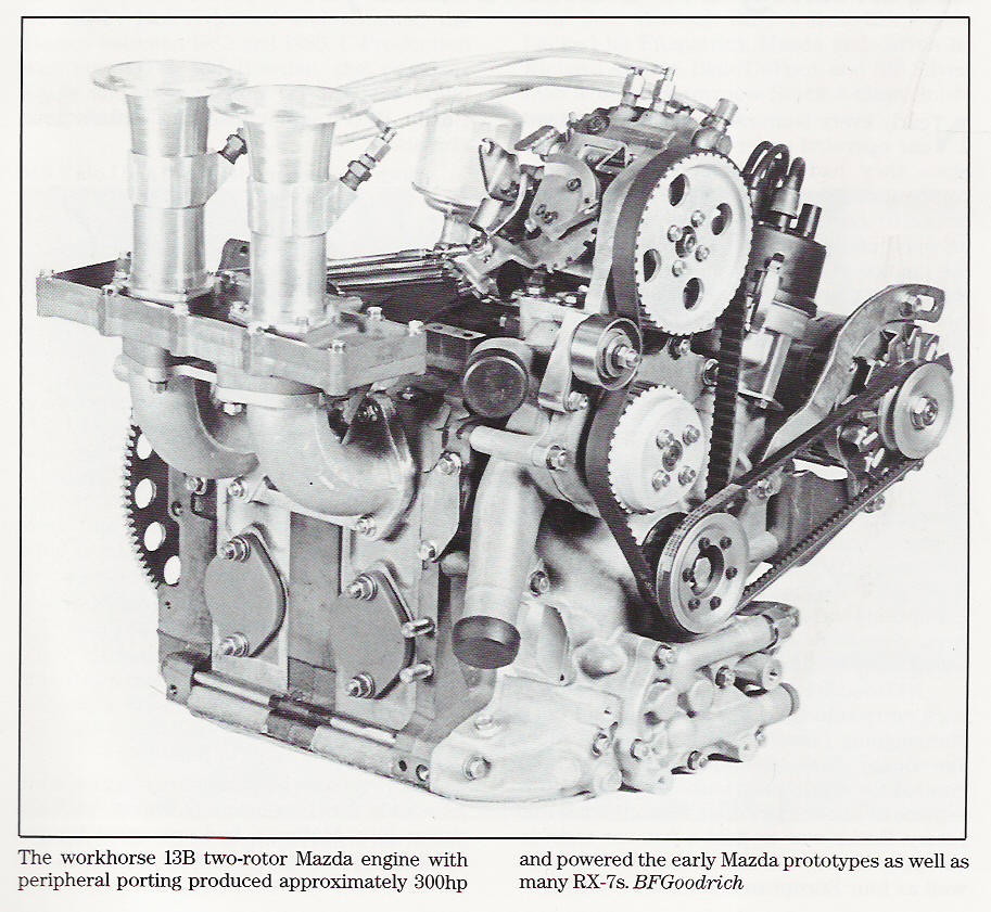
In the attached pictures: These pictures are taken before the parts where
polished, painted, and in the case of the throttle, welded. This throttle
shown goes on the PSRU side, the accessory side throttle is reversed. Thus a
coupler join the throttle shaft together over the center housing. You can
see that throttle plate when closed reaches a smidgen below the throttle
plate step bore. This bore interfaces with a protrusion on the runner collar
so the positioning is correct. (left of picture). Naturally gasket material
will be used. The collar will have the FRP runners bonded to it when I
figure out how to cast them accurately. Probably use the wash out internal
mold idea. The tube on the right is the double O-ring sleeve that fits
within the intake housing bore. Notice the taper on the top inside. This is
so the throttle plate clears the edges when it opens into the 2" ID sleeve.
The throttle and the intake runners are slightly larger in ID than the
intake sleeve. 53mm verses 51mm. This was done to compensate for the cross
sectional area loss the throttle plate creates when fully open. The throttle
plate support shafts were designed in a manner to minimize the cross
sectional area when open. The central hole will most likely be enlarged so
that the engine may idle from the air entering there. This idling hole may
be a bad idea as it isn't found in traditional plate throttles.
A construction challenge: The stainless shaft and throttle plate had to be
TIG welded in situ. With a jig and the skill of my friend's (small dextrous
hands), he was able to do a fine job. Bearings are a hard teflon material,
called BEAREE from NTN Bearing company. Other pictures show the throttle
plate in various positions. Four M5 size studs screwed and sealed into the
rotor housing retain the throttle, the insert sleeve as well as the intake
runners.
Doug in Japan
13 MM is over a half inch thick. Surely your butterfly is not 1/2 inch
thick.
When I gave a lecture at the World Motor Sports symposium in Oxford
to the top F1 race car engineers there was a guy from Porsche that
gave a lecture on butterfly valves among other things. Here are a couple
of pictures. I also have an animation but it is 4 meg. You should have
used our low cost and easy to make slide throttle. I just finished a turbo
engine with slide throttle for a guy in Saipan.
Every wart in the intake manifold comes right out of your pocket in precious
gasoline burn and range.
What were you thinking? :)
Paul Lamar
Paul,
Thinking? I share the same philosophy as Steve and Everett. The throttle
plate is 1mm thick and the effective installation puts it nearer the port
opening than the slide throttle. Turbulence downstream on an open P-port an
inch away is quite different than that experienced in a Porche convoluted
intake manifold. Slide throttle wouldn't fit. Basically I studied your
design, designed a more compact one and eventually gave up on them because
of interference problems. Sure Wide open the
slide throttle has the maximum merit. On partial throttle it also has some
turbulence issues though. Sort of like opening a sliding barn door on a
windy day. If you truly believe you will be flying your turbo charged air
craft at WOT most of the time then more power to you:)
Doug in Japan
What happened to the 13 MM?
You spend 99% of the time wide open at altitudes over 8000 feet with an NA engine.
Butterfly drag is a butterfly drag regardless of how far from the port it is.
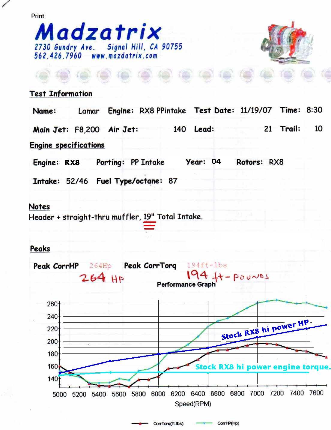
These dyno charts plot the HP and Torque of a p-port engine built like Everette's and
one of our p-port carb engines. The Power Sport engine is putting out only 105 HP
per rotor.
With all due respect Everette and Steve did not invent the Teflon slide throttle.
I did. The more expensive ball bearing slide throttle was chosen by Mazda from the get go
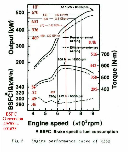
back in the early 80's when they were seeing 150 HP per rotor at 9000 RPM.
At 690 HP the slide throttle Le Mans engine is a record at 172.5 HP per rotor.
We copied it as close as we could given a 2.85:1 gear box tuned for 7500 RPM.
We are seeing close to 130 HP per rotor at only 7200 RPM with the P-port RX8
engine rather than the 9000 RPM of the Le Mans engine. At 7250 RPM the Le Mans
engine is putting out 148.5 HP per rotor.
With your 3:1 Bell 47 final drive you are going to need all the high RPM and
HP you can get to get that flying Yacht on the step and out of the water :)
I don't know how you missed all this. You must have been in Nepal.
Do you have battery powered Internet in Nepal? If so try reading the web site
once in a while by candle light on those long dark nights when there is nothing
else to do :)
http://www.rotaryeng.net/intake.html
BTW if that Bell 47 final drive does not work out for you you should
build one of our new 3.12:1 gear boxes. They are coming along fine
we should have four.... four inch diameter 7075 T173 aluminum prop shafts
done next week. They are designed for up to 5 new hollow carbon fiber
Sensenich prop blades.
Paul Lamar
The hole in the throttle plate is used on bridge ported race engines to
achieve nearly normal
idle RPM. In that case the hole is at the edge of the plate just above the
drilled idle passages in the carb body. This allows the edge of the
butterfly to be in a nearly closed position just above the idle drillings rather
than below the drillings where no vacuum is generated, and that more common
Rummmp-Rummmp- Rummmp is heard. The hole provides a finer adjustment than
attempting to hold a large butterfly at a specific angle.
Lynn E. Hanover
Lynn, are you in South America?
Paul Lamar
--
The Rotary Engine NewsLetter. Powered by Linux.
ACRE NL web site.
http://www.rotaryeng.net
Youtube key word PaulLamar2
Copyright 1998-2011 All world wide rights reserved.