Hi Paul,
I've finished my (13mm) thick butterfly throttles and I'm trying to
decide if an over the top variable induction pipe (runner) system
will have any merit. Near sealevel yes, but what about up high?
Does air pressure within the airbox affect the optimum length?
Doug in Japan
Frequency = speed-of-sound/wavelength
An alteration in either speed or wavelength will result in an
alteration of the natural frequency.
You can calculate it from this chart.
Why 13 MM ?
Paul Lamar
Paul,
Thanks. I recently found out that the total volume of the air box
and ducts, filter etc. is important. Especially for a turbo charged
engine. Too little and the air resistance goes up so the engine is
starved. Too much and the response time is lowered, or the engine
bogs. For aircraft I would imagine it is better to err on the side
of being to big.
Here is a handy calculator I discovered for the speed of sound calculations.
http://www.sengpielaudio.com/calculator-waves.htm For simpler
calculation based on temp. only try here.
http://www.sengpielaudio.com/calculator-speedsound.htm I used this
to determine that at cooler temperatures (up high) the tuned length
As for why the 13mm thick throttle, the short answer is that number
is the minimal thickness that would work without throttle plate
interference. The throttle plate as designed is actually slightly
elliptical. Edges are slightly beveled to reduce air resistance.
I'll fine tune the shape once I put it on the flow bench. Long
answer: Having the throttle directly on the housing and having the
throttle plate swing down inside the inner sleeve is about as close
to the intake port as I could get it in the intake size I wanted. I
explored several variations of slide throttles but was unhappy with
the large amount of real estate it required.
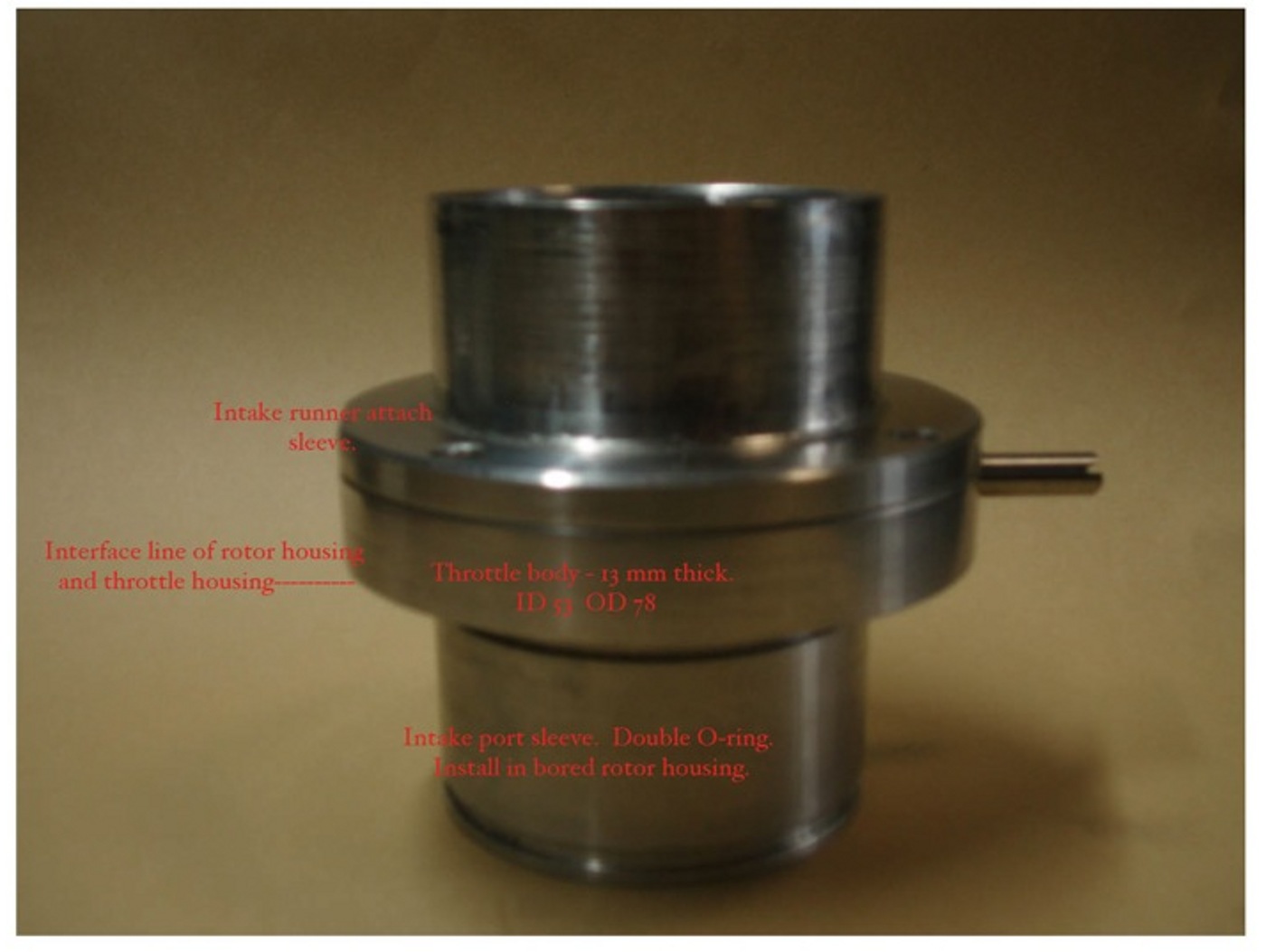
In the attached pictures: These pictures are taken before the
parts where polished, painted, and in the case of the throttle,
welded. This throttle shown goes on the PSRU side, the accessory
side throttle is reversed. Thus a coupler join the throttle shaft
together over the center housing. You can see that throttle plate
when closed reaches a smidgen below the throttle plate step bore.
This bore interfaces with a protrusion on the runner collar so the
positioning is correct. (left of picture). Naturally gasket material
will be used. The collar will have the FRP runners bonded to it when
I figure out how to cast them accurately. Probably use the wash out internal
mold idea. The tube on the right is the double O-ring sleeve that
fits within the intake housing bore. Notice the taper on the top
inside. This is so the throttle plate clears the edges when it
opens into the 2" ID sleeve. The throttle and the intake runners are
slightly larger in ID than the intake sleeve. 53mm verses 51mm.
This was done to compensate for the cross sectional area loss the
throttle plate creates when fully open. The throttle plate support
shafts were designed in a manner to minimize the cross sectional
area when open. The central hole will most likely be enlarged so
that the engine may idle from the air entering there. This idling
hole may be a bad idea as it isn't found in traditional plate throttles.
A construction challenge: The stainless shaft and throttle plate
had to be TIG welded in situ. With a jig and the skill of my
friend's (small dextrous hands), he was able to do a fine job.
Bearings are a hard teflon material, called BEAREE from NTN Bearing
company. Other pictures show the throttle plate in various
positions. Four M5 size studs screwed and sealed into the rotor
housing retain the throttle, the insert sleeve as well as the intake
runners.
Doug in Japan
13 MM is over a half inch thick. Surely your butterfly is not 1/2
inch thick.
When I gave a lecture at the World Motor Sports symposium in Oxford
to the top F1 race car engineers there was a guy from Porsche that
gave a lecture on butterfly valves among other things. Here are a couple
of pictures. I also have an animation but it is 4 meg. You should
have used our low cost and easy to make slide throttle. I just
finished a turbo engine with slide throttle for a guy in Saipan.
Every wart in the intake manifold comes right out of your pocket in precious
gasoline burn and range.
What were you thinking? :)
Paul Lamar
Variable length intake as per the Le Mans engine is for a broad torque range
in automotive use. For aircraft, it is just more weight, as you will run at a
fairly narrow and consistent RPM range. The throttle plates close to the rotor
housing is also automotive derivative for throttle response. Again not
necessary for aircraft. For my money, I would use a p-port with a similar
aftercooler set-up like Paul shows in his attachments with the single slide
throttle between the turbo and aftercooler.
Between design time, machining and the welding; you have a lot invested. I
hope it works for you.
Dale Davies
Dale,
Yes, I basically agreed with your line of reasoning and thought the same
until I got deeper into the project. After noticing the significant risk of
depending on a turbocharger functioning full time, I wanted the engine to be
able to function well without it. Consider an obstruction in the filter
intake from debris and this would necessitate alternative air. Common
aircraft engine design point. However it makes no sense to introduce that
alternative air before a slide throttle and after the blow off valve.
Intercooler restriction, like a poorly designed throttle creates power loss.
Delivering that alternative air to the air box would be the better choice
with the throttles downstream. Air moves to the path of least resistance.
Thought has to If the flight mission is for maintaining limp home power, or
land immediately mode, then my points are mute.
Throttles: Somehow I got convinced that the P-port engine would not idle
well without the throttles right near the intake port. Sure the engine
operates at high rpms most of the time but I'd like to have an engine idle
that is kind to the PSRU and is attractive to the aviation community.
"Install a slide throttle close up" became the mantra on this forum. That
is, until Paul made up an engine to sell to a novice and didn't follow his
own advice:) WT?
I also hear repeatedly that a slide throttle fully open has less restriction
than a butterfly when fully open. That statement in itself is not true. The
answer should be "it depends." It depends on the butterfly throttle design,
size, and the intake profile, and runner shape before and after the
throttle. For instance The teflon slide test throttle ID I believe is 4.8cm
in diameter which equals 18 square cms in area. My test throttle is 53mm ID
(22 sq.cm) minus the plate and support shaft (less than 1cm sq.) for a total
area of 21sq. cm. Is bigger better? Sorry honey, not in this case:) These
facts by themselves mean nothing. Only by flow bench testing each and every
intake system design point can any intelligent claim be made about the
system.
I have no vested interest in being right but I do want to make the very best
engine possible. I'll be the first to change out any part if it doesn't
perform well. However with all of the differing opinions I have been
listening to over the years, I've decided to test and verify each and every
design point. This has added years to my project. But then again, hobbies
are not meant to be scheduled.
VLI: I want both maximum power and maximum BSFC in the engine meant to
perform for 15 to 16 hour flights. Correct me if I'm wrong but that would
entail different length induction pipes. Note* A main factor in Mazda's
Leman's win was the car's ability to get good gas mileage.
Cheers
Doug in Japan
What happened to the 13 mm throttle plate for the 3rd time? :)
"That is, until Paul made up an engine to sell to a novice and didn't follow his
own advice:) WT? "
That was a side port turbo engine I had and not a p-port. Side port engines idle
fine wherever the throttle is located in the intake system.
To be kind to the PSRU your idle speed should be 1800 RPM or higher.
It is quite amazing that this idle speed is common to different brands
and types of PSRU's. We found that out with the Rotamax engine.
Same idle speed required while the gear box was a double spur reduction type.
Of course the area of the pipe is a factor. We used 2 inch OD 50.8 mm the same
as the Lemans engine but you could build a slide throttle with 2.13 OD (54mm) or
even 2.25 inches OD. 180 degree bends are available from Burns Stainless in
both those diameters as well. No excuse for a butterfly.
2.25 inches OD is 57.15 MM which is larger than the 55 mm OD you are using.
Anybody is free to make a simple Teflon slide throttle in any diameter.
They are easy to make with simple tools.
The problem is the amount of side support the apex seal gets as it
passes over the intake port hole. The rotor housings are only 80 MM wide so
your 53 mm ID leaves only an untested side support of only about 14 mm on each side.
Around a little over 1/2 inch. Good luck with your larger hole and apex
seal bending. We know the LeMans configuration works.
The Le Mans p-port slide throttle engine had a best BSFC (.47) of any rotary engine
built so far. It won the race outright with the amount of fuel allowed for the race.
Good luck besting .47.
Do you want maximum miles per gallon or merely the best BFSC?
If you design the intake system for max power you will get
best BSFC at peak torque. In our case best BSFC and best torque
occurs at 6000 to 6200 RPM while peak power is 7500 RPM.
Coincidently 6000 RPM is where the rotor bearing loads are a
minimum so that is a good cruise RPM. Bearing loads are higher
both above 6000 RPM and below 6000 RPM. In the old days
running it WOT below optimum RPM was called lugging the engine.
Most airplanes have a best climb rate down around 100 to 130 MPH.
That is where excess HP is a maximum. Overall drag is a minimum.
AKA the drag bucket.
That is probably near where you will find the best MPG.
What you need do is slow the RPM with prop load to achieve
that best MPG cruise speed. Mark S does that all the time
with his 3 rotor slide throttle p-port Lancair ES.
If the engine RPM is significantly below 6000 RPM at that point you
will need trombone style intake similar to the LeMans engine runners
but longer yet to optimize the torque and BSFC at that new lower RPM say 4500.
Paul Lamar
Paul,
You are misinterpreting my words. Again:) Perhaps I'm writing in Japlish.
That's why I spent the time to take the pictures. The throttle, or throttle
'body' to be precise is 13mm thick. The throttle 'plate' is only 1mm thick.
The inside diameter of the throttle body is 53 mm. The inside diameter of
the housing sleeve insert, tapers immediately down to 50.8 mm. This is
exactly 2" and exactly what one the Japanese designer of rotary engine fuel
system recommended to me to use. Yes, one can use a smaller size if you are
happy with 250hp and are prop limited to 7500 rpms. The engine will not
reach 300hp at or near 8400 rpm in a N/A configuration though. Yes, I
recognize that has not been your goal but I suspect that with your new
spiffy 3.1:1 PSRU it soon will be:)
Yep, the upstream air duct could be made of aluminum pipe but I'm going for
a tight package and will need to get creative to keep radiuses under
control. Design is pending and I'm considering, computer flow analysis and
then 3-D printing the master blank to get it correct. BTW, I like the idea
of the intercooler married to the air box. I plan to do that as a space
saving idea as well.
Now as for variable length manifolds I don't mind fabricating one for
testing best lengths but there seems to be a disconnect in your stated
performance logic. Either that or I'm looking at the information wrong. It
wouldn't be the first time:) I think it is because you have always
considered peak rpm to be about 7500 and the length/verses peak torque
discrepecies in runner lengths are smaller.
According to the Leman variable length intake manifold chart, the best power
torque peak occurs at 16" or 406mm length. The bell shape curve (labelled 0
extension) does not vary significantly from 8300 to 8500 rpms. *Note: For
the new comers note that all the potential bell curves are drawn in but we
can extrapolate from what is. Now, assume as you suggested we keep the
runners set at this best power length. What happens when we pull the rpms
back to 6000 or so? Well, the torque curve plummets and even if we could
imagine the rest of the curve to be flatter than the 175 length curve,
torque would be dismal, perhaps in this engine down 100 ft/pounds and hence
horsepower would suffer. If indeed 6000 rpms is the low friction sweet spot
for the two rotor as well as the Leman's engine, then the engine would
require a runner 175mm (6.8") or so longer to peak the torque at 6000 rpm.
This translates to a total runner length of 22.8" to maximize BSFC and
torque at this engine speed. These runners were
Is the Lemans approach to a variable tuned intake pure genius or am I over
imagining the merits for aviation? Mazda took what they learned and applied
it to the Renesis engine, albeit with in a different technique. Goals were
the same. Maximize performance at different rpm settings. The auto engine
has three settings. Perhaps we only need two. Call me crazy but aren't we
talking about a ten horsepower difference here? Aren't total efficiencies of
an engine a product of many subsystem efficiencies? If turbo-compounding is
be considered wouldn't it be wiser to maximize the efficiency of the intake
and exhaust system first?
Doug in Japan
Yes I think you are on to something there. You have been living in Japan so
long you are starting to think in Japanese :) Top to bottom instead
of left to right :)
"I've finished my (13mm) thick < butterfly throttles and I'm trying to
decide if an over the top variable induction pipe (runner) system
will have any merit."
If you wanted to be clear in English you would have used the word long
instead of thick as in:
"I've finished my (13mm) long < butterfly throttles and I'm trying to
decide if an over the top variable induction pipe (runner) system
will have any merit."
Of course if the inside diameter is 53 mm the real length of the throttle
body wide open is 53 mm and not 13 mm. The plate extends into the rotor
housing on one end and into the runner on the other. Now I am sure you did
not intend to have the rotor hit the throttle plate so I am also sure your
throttle body will need to be longer than 13 mm :)
I think you need to spend some time learning Rhino 3D so you can
communicate your ideas better. I assume you have finished
your book and your myriad other avocations and duties
are now at a minimum. (Are you going to Nepal this year again?) I
could be wrong. If so here is a bit of fatherly advice.
IMHO you need to focus on one thing at a time :)
Now back to home building a Sea Wind aircraft.
It all depends on a constant speed or variable pitch
prop. A fixed pitch prop fully loads the engine at only
one RPM. WOT RPM. Are you planning to use a constant speed
prop? It must be an electric version as the Bell 47 final drive you
have will not support a hydraulic constant speed prop.
Everything changes in a fundamental way if you are.
Paul Lamar
Paul,
Ok Pop. Good advice. I've been to Nepal twice this year already. Next year
in the snowy months I'll head out there. That project is nearing completion
and I have a manager now. Yes, the book is finished and goes on sale on
Amazon.com this month, but marketing issues keep me entertained. Wednesdays
are rotary engine machine shop days, and Saturdays are SeaWind FRP days.
Sundays are honey dos. You know about those right?
Rhino for the Mac is good, but with my skill set I found it too time
consuming to make a point. Sorry! I try to use it when I'm actually ready to
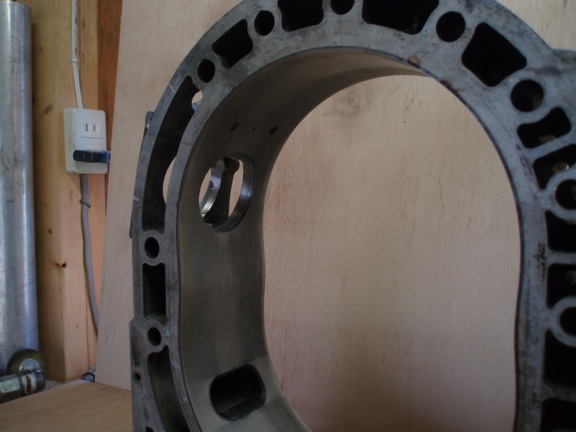
make a part. Photographs of actual parts are worth a thousand words, but in
some cases apparently not. Below are two pictures of a rough TEST-housing I
made last year. This housing is scrap and was only made to test hole
placement, jig accuracy and soon air flow testing. Not shown are the four
studs that hold the throttle body to the housing and the two positioning
holes for the injector sleeves hold down plate. The central hole between
the injector performs two functions. It is a center drilled bolt and
provides the air passage way for a fitting to connect to the MAP sensor
hose. The second function is to fasten the injector sleeve hold down plate
in place.
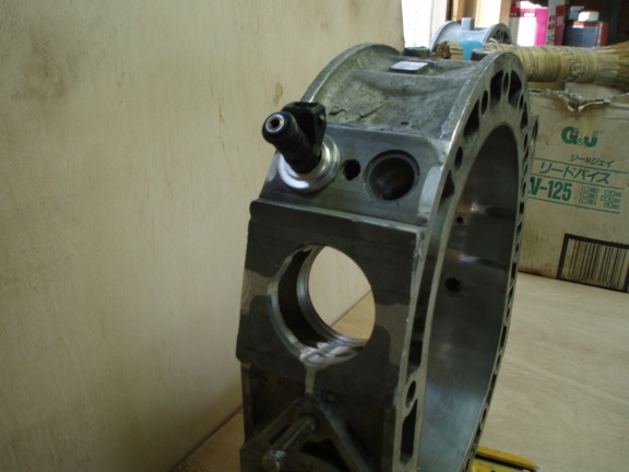
The top flat will have a hole, thin stainless tube and outer fitting for
hydrogen injection testing. Not 100% Additive only. If no merit is found I
will not use it. The other picture is the stack of parts as they would
appear with the rotor housing. Of course you don't see the lower sleeve
insert. *Note: Throttle plate upon full opening comes to within 22 mm from
inside housing. Enough clearance I'd say:)
I'm working on the stainless fuel rail tomorrow. Why stainless? It's a
flex fuel engine.
So back to the discussion of VLI. Yes, of course an electric pitch
controlled C/S prop. Prop pitch setting controls engine rpm. Each engine
rpm has an ideal runner length for achieving best torque and hence best
potential BSFC at that particular rpm. That is the goal for maximizing
engine efficiency. Right?
Maximizing mpg is another story of course. That is influenced by flight
conditions and altitude. I agree that conserving fuel means one has to
throttle back to drag bucket speed, cross ones fingers and legs if you get
my drift:) Speaking of which. This guy in the following link could have
used your advice. What a waste. So close. Glad he made it out alive though.
Having a plane that floats is one of the reasons I chose the Seawind. It may
not sink but I wonder how long the wings would stay attached in rough seas.
Deploy the storm parachute anchor and head downwind? You know there is a
calculation and fuel management technique in long distance flying whereas
one can make a concrete go - no go decision at half-way point. The decision
to turn back is always the hard one. Slowing down and prolonging the agony
is also psychologically difficult but necessary to save one's bacon, and
Cessna.
http://www.wtoc.com/story/15646907/plane-ditches-in-ocean-off-hawaii-pilot-rescued
Doug in Japan
The tig welded in stainless steel p-port tube is a major improvement
in ease of installation, reliability and freedom from leaks over the old Devcon
based p-port. It is REAL easy to do. We have done well over a dozen so far.
http://www.rotaryeng.net/Welded-steel-p-port.html
Given your good skill level at tig welding it would be a piece of cake for
you to do.
I would use it if I were you.
Paul Lamar
--
The Rotary Engine NewsLetter. Powered by Linux.
ACRE NL web site.
http://www.rotaryeng.net
Youtube key word PaulLamar2
Copyright 1998-2011 All world wide rights reserved.

