Paul,
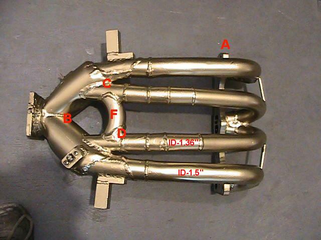
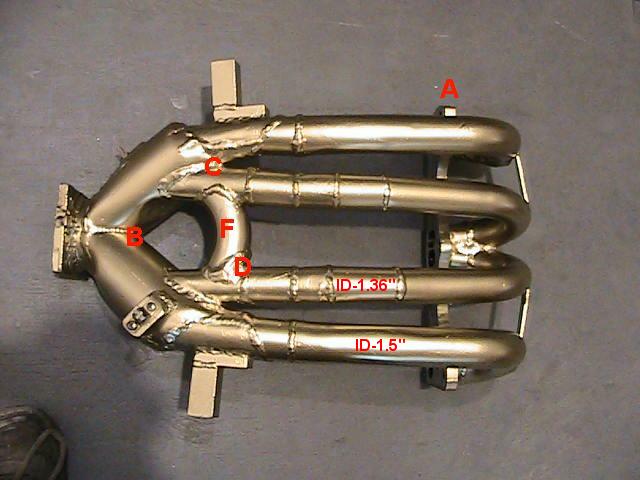
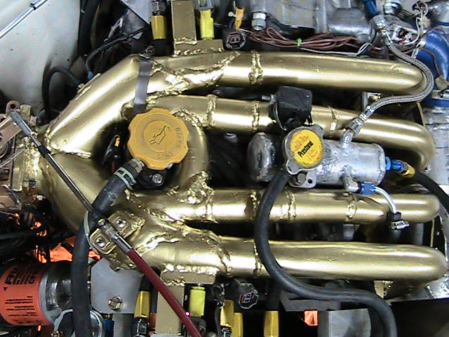
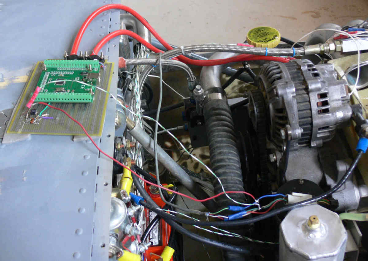
Here is a photo of my latest intake manifold. Lengths are the following.
A to B is 21"
A to C is 17"
A to D is 16.25"
The length inside block is 3" so we must add the 3 inches to the above
lengths.
The bridge marked F was added later and it made no difference.
The outside of the manifold is rough but the inside is smooth, it has been
modified so many times.
From the readings on my EM2, the data in addresse 78 to 85 is a constant
124.
Below address 78 the data is 55 or less.
Above address 85 the data goes down, at address 103 the data is -10
During takeoff the controller is at address (between 100 and 103) depending
on map.
Is it safe to say that the tuning effect of the intake manifold takes place
where the data is highest ie between address 78 and address 85, where the
injectors supply the most fuel?
Thanks
Rino Lacombe
Renesis powered Glass Goose
Well first let me say there are a lot of strange things going on in there
aerodynamically.
If it is designed as a dynamic chamber and we can assume it is actually working
the effective length is twice the physical length putting the max torque
down around 3000 RPM and the peak HP roughly at 5000 RPM.
However if it is not working as a dynamic chamber or only partly working as a
dynamic chamber no telling what is happening. If you are interested in what
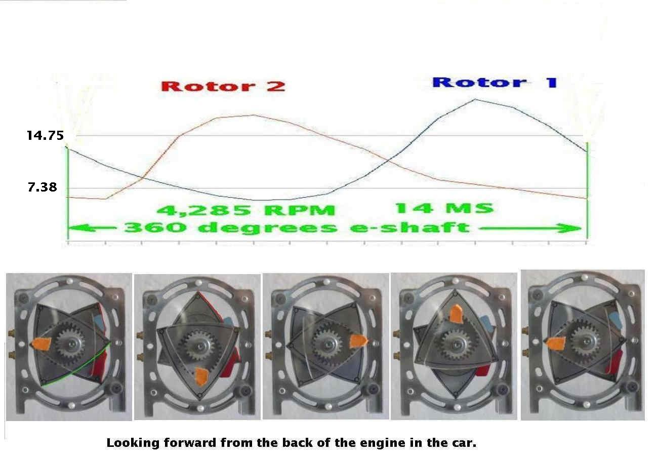
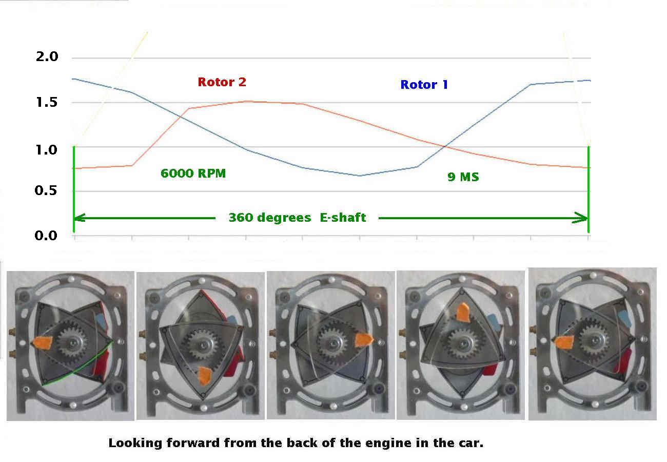
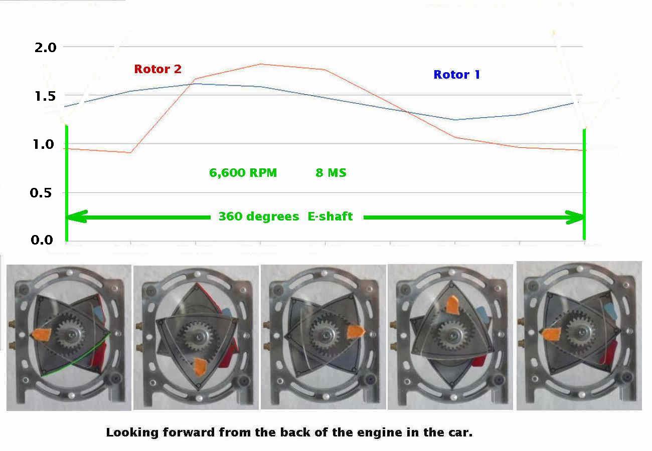
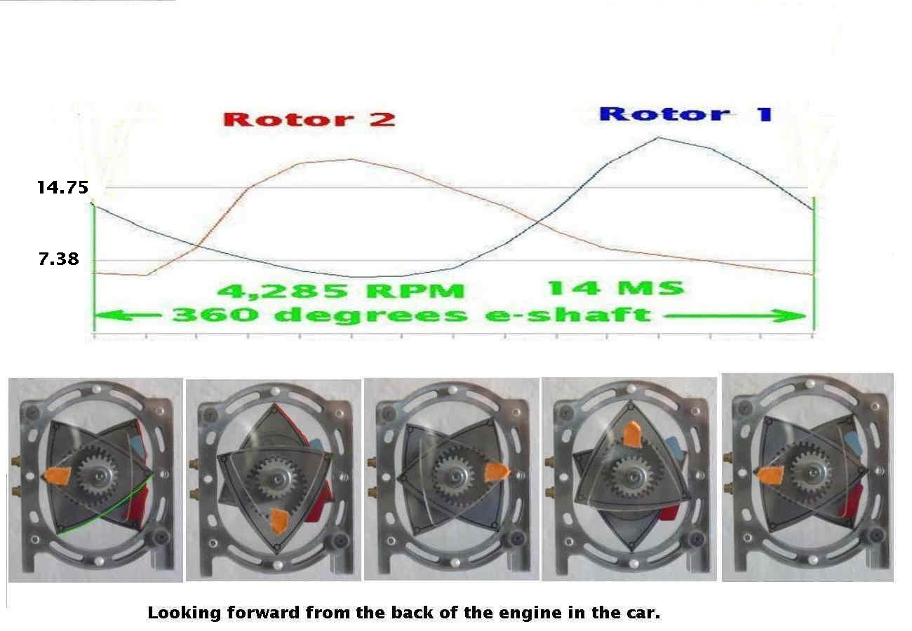
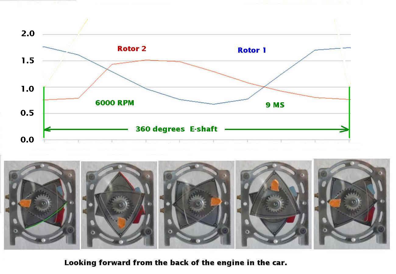
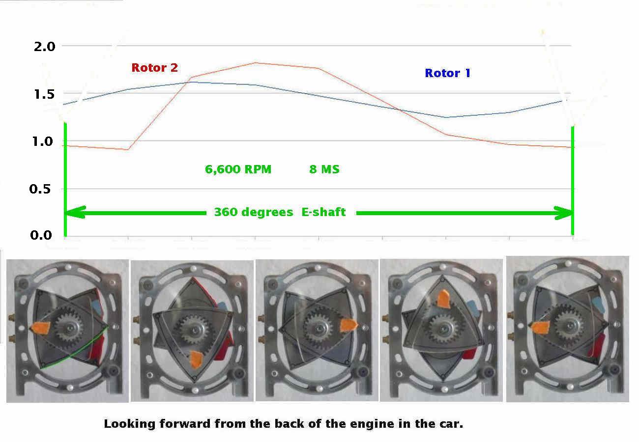
is actually happening you can use a data aq system to measure the pressure
as a function of engine RPM.
http://www.hytekautomation.com/
Here are some graphs on that technique.
And yes the EM2 readings reflect the amount of fuel injected I think.
Or at least it should be as Tracy is not too clear on all this stuff.
Where are the pressure taps located? What are the HP, EGT, manifold pressure
and RPM read outs at these trim readings?
The mixture map values are basically based on manifold pressure, RPM and intake
air temperature. All of these determine the amount of fuel injected. The data in
the tables is used to fine tune the mathematically determined injection quantity
required by the engine. At least I think that is the case for most EFI systems.
Tracy calls this "mixture correction" so it sounds like he is doing it
in the traditional way mentioned just above.
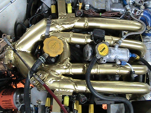
If I were you I would forget the dynamic chamber and cut off the tubes east
of the oil filler neck and add a simple plenum there. Then use the apex
seal oil holes as manifold pressure taps to determine the actual amount of
air getting into the engine.
Paul Lamar
--
The Rotary Engine NewsLetter. Powered by Linux.
ACRE NL web site.
http://www.rotaryeng.net
Youtube key word PaulLamar2
Copyright 1998-2011 All world wide rights reserved.