Is there any information on the website showing the timing of the
intake
and exhaust port relative to eshaft rotation? I am specifically
interested
in the overlap and the e-shaft angle at which the apex seal clears the
exhaust port. Inspired by your 555 system, I have designed a simple
digital
converter to convert MAP to pulse width for controlling the
injectors. We
know that the volumetric efficiency of the p-port at 6000rpm is 120%.
I am
wondering how much of that 120% is represented by intake air passing
through
the chamber and out the exhaust during overlap. If this occurs at
all, it
would improve efficiency to minimize the amount of fuel in the
bypassed air,
suggesting that the injectors should be opened after the exhaust is at
least
partially closed
Victor Roberts
I don't have the numbers for the timing but it is exactly the
same as the Le Mans 4 rotor.
http://www.rotaryeng.net/Mazda_R26B_US.pdf
http://www.rotaryeng.net/Welded-steel-p-port.html
The numbers can be derived from the scale dwg in this last link.
The exhaust and intake P-ports in a rotary never really close.
In that regard it is more like a turbo jet.
What air does not go in one chamber goes in the next.
In a tuned rotary engine however the max pressure in
any given (One of 3) compression chamber depends on the RPM,
pipe length and pipe diameter.
http://www.rotaryeng.net/Mazda-p-port-press-wave-enhanced.jpg
The best place to measure this pressure is the apex oil injector
holes just above the p-port intake. Of course one is not using
these holes for oil injection. One mixes the apex oil with the fuel.
I am coming back to the 555 system and adding a single chip computer
that
has the sole job of adjusting the mixture using a USB port and
storing the trim data in a spread sheet format. The program becomes
extremely
simple and easy to comprehend. Merely a look up table in the single
chipper.
Henry Nee came up with this great idea and people can email and
share
trim
tables. Any number of trim tables can be stored in one's PC. It also
makes
editing the trim table simple as you do it in your PC using a spread
sheet
program. This should greatly speed the tuning of your engine and
similar
installations can use the same trim table. We can put them on the
web
site
for rapid download. Parameters affecting the trim are type or
drag of
the airplane, diameter and pitch of the prop, intake pipe length and
gear
ratio used. Assuming all are using a p-port.
Paul Lamar
Victor, I have seen the port timing numbers in the Kenji Yamaguchi
(SP?)
papers. I think there is a link on Paul's site and possibly on
Craigs
Rotary List site also.
george grimes
http://www.turborx7.com/porttiming.htm
cbeazley
From Mark Warner's book Street Rotary, page 34, here's a port timing
chart of various Mazda models. Here's a link to the book:
http://www.amazon.com/Street-Rotary-HP1549-Horsepower-Reliability/dp/
1557885494/ref=sr_1_1?s=books&ie=UTF8&qid=1321457929&sr=1-1
Tom Sash
Much of this is useless info as it makes no sense to port a side
port engine for aircraft use. If you need to take the engine apart
to port it you might as well P-port it. The p-port intake manifold and
slide
throttle are easier and cheaper to make than a side port manifold.
You wind up with 25% more power and a better BSFC.
Most of the road racers need it because p-ports are outlawed due to the
rotaries over helming domination of most road racing classes.
Only in the Rolex GT class are RX8 3 rotor p-ports allowed and then they
suffer from extra ballast and an enforced red line 500 RPM below the
street
engine.
Paul Lamar
These numbers for the Mazda P-port are bogus.
As Paul has pointed out, there is an overlap of intake timing between
adjacent rotor faces.
When the apex seal is in the center of the port, two chambers are open
to the intake. From this position, after 360 degrees of shaft rotation
the rotor face which was just beginning intake before the rotation would
still be half open to intake after the rotation. The intake period
exceeds 360 degrees of eshaft rotation.
Reference these numbers to after TDC and it becomes apparent they cannot
be true.
The intake opening at 86 BTDC is 274 degrees of e-shaft rotation After
TDC.
The intake close of 75 ABDC is 255 degrees After TDC.
This gives us 19 degrees of shaft rotation where neither is open.
For the exhaust, opening at 73 BBDC is 107 After TDC, and closing at 65
after TDC - 42 degrees of shaft rotation when no exhaust occurs.
It appears to me that the interior circumference of the rotor housing
is about 27 inches; so 360 degrees of shaft rotation is 9 inches. A
two-inch port opening then requires 80 degrees of shaft rotation to
transit, so the trailing port opening occurs 80 degrees ahead of the
leading port closing. The intake period including overlap is about 440
degrees of shaft rotation.
The exhaust port appears to be half the size of the intake, so 400
degrees of shaft rotation from opening to closing.
Tell me where I am wrong.
Victor Roberts
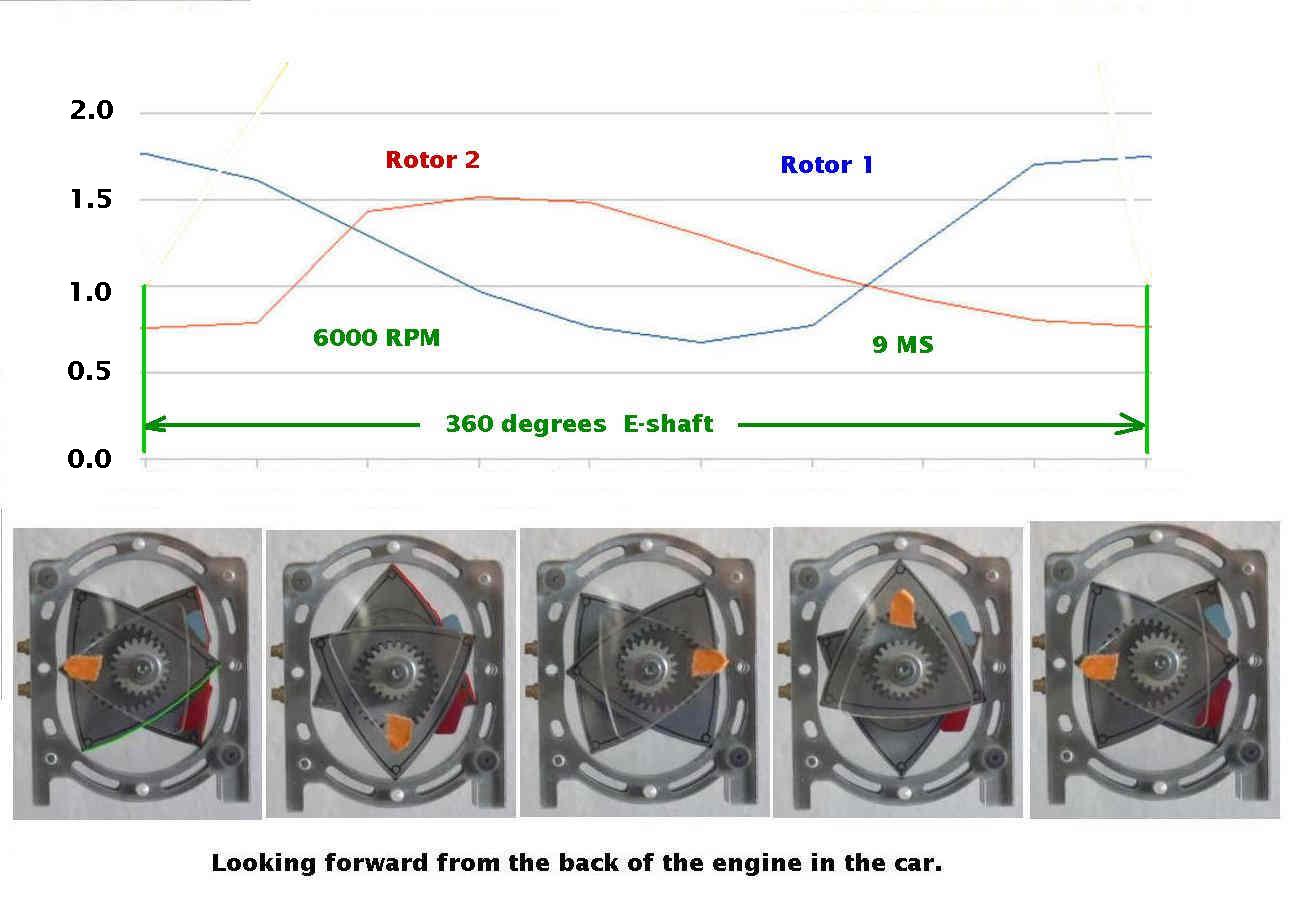
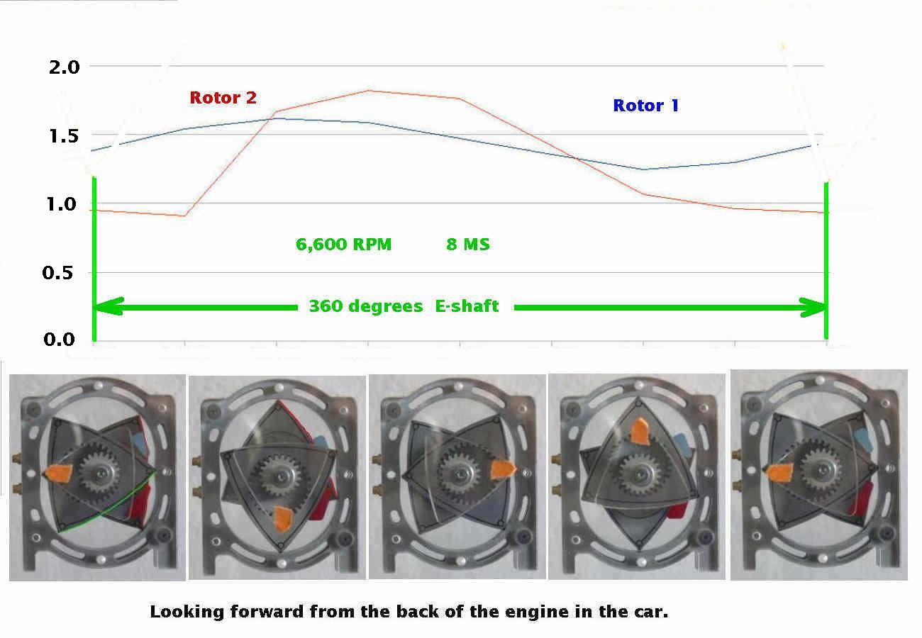
The intake period is 270 degrees of e-shaft rotation as are all other
strokes. In a p-port there is a depression in the rotor face that
connects the intake port with the exhaust port. Surprisingly the
pressure in the intake is higher than the pressure in the exhaust.
Therefor air flow, if any, goes from intake to exhaust in theory.
However air has mass, friction, adhesion and inertia. So what
goes where and how much is arguable.
Here is a Racing Beat 3 rotor P-port turbo making 900 HP as I recall.
Some of the end housing are aluminum.
Note the size of the turbo charger :) One would think the injectors,
being on the plenum side of the long intake runners, would lose
fuel to the exhaust. Jim Medere told me that was not the case.
In fact the BSFC was slightly better with the injectors at the start
of the runners. I can't wait to see what happens when Dave Lemon
builds a welded p-port with a slide throttle RX8 engine. Should be
around 600 HP or more instead of only 420 HP :)
As I recall the 3rd gen RX7 stock body land speed record at 268 MPH was
set with a 3 rotor, 3 turbo side port engine making only about 750 HP.
It had an ice water inter-cooler as I recall.
BTW a picture taken from my C182 made the centerfold of Pop Sci
mag the year of the flood at Bonneville. That was the first year the
recording holding R.B. 3rd gen 3 rotor RX7 showed up.
http://www.youtube.com/user/PaulLamar2#p/u/11/JUf_aWVVl7o
With our man on here Csaba Csere narrating no less.
I got my 2 cents in at the end.
Paul Lamar
OK. Just as the piston 4-stroke has valve overlap and does not operate
on precise 90 degree intervals, doesn't the p-port rotary have an
effective overlap?
You have stated many times that the intake flow is continuous. If the
effective intake is only 270 degrees, the flow stops for 90 degrees of
every shaft rotation.
I'm not attempting to assert a position, just trying to understand the
dynamics of the flow. If the flow is effectively continuous, as you have
often asserted, how can the intake be less than 360 degrees?
Victor Roberts
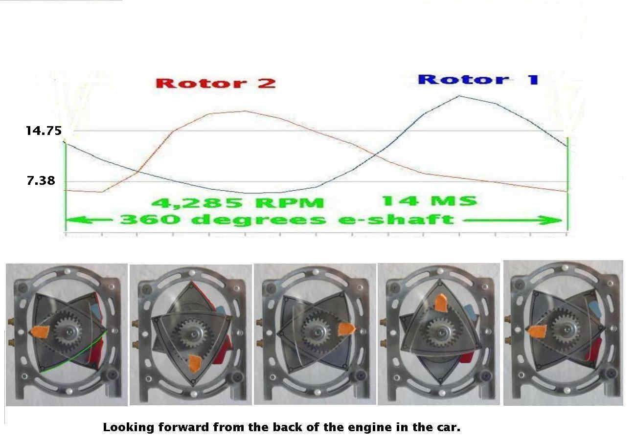
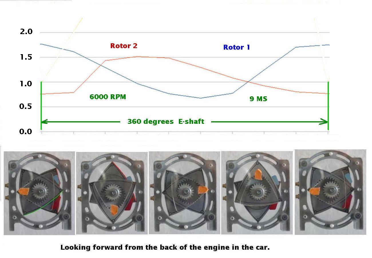
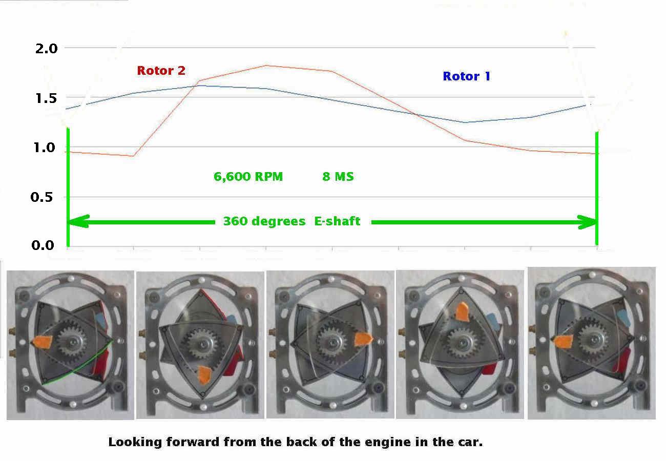
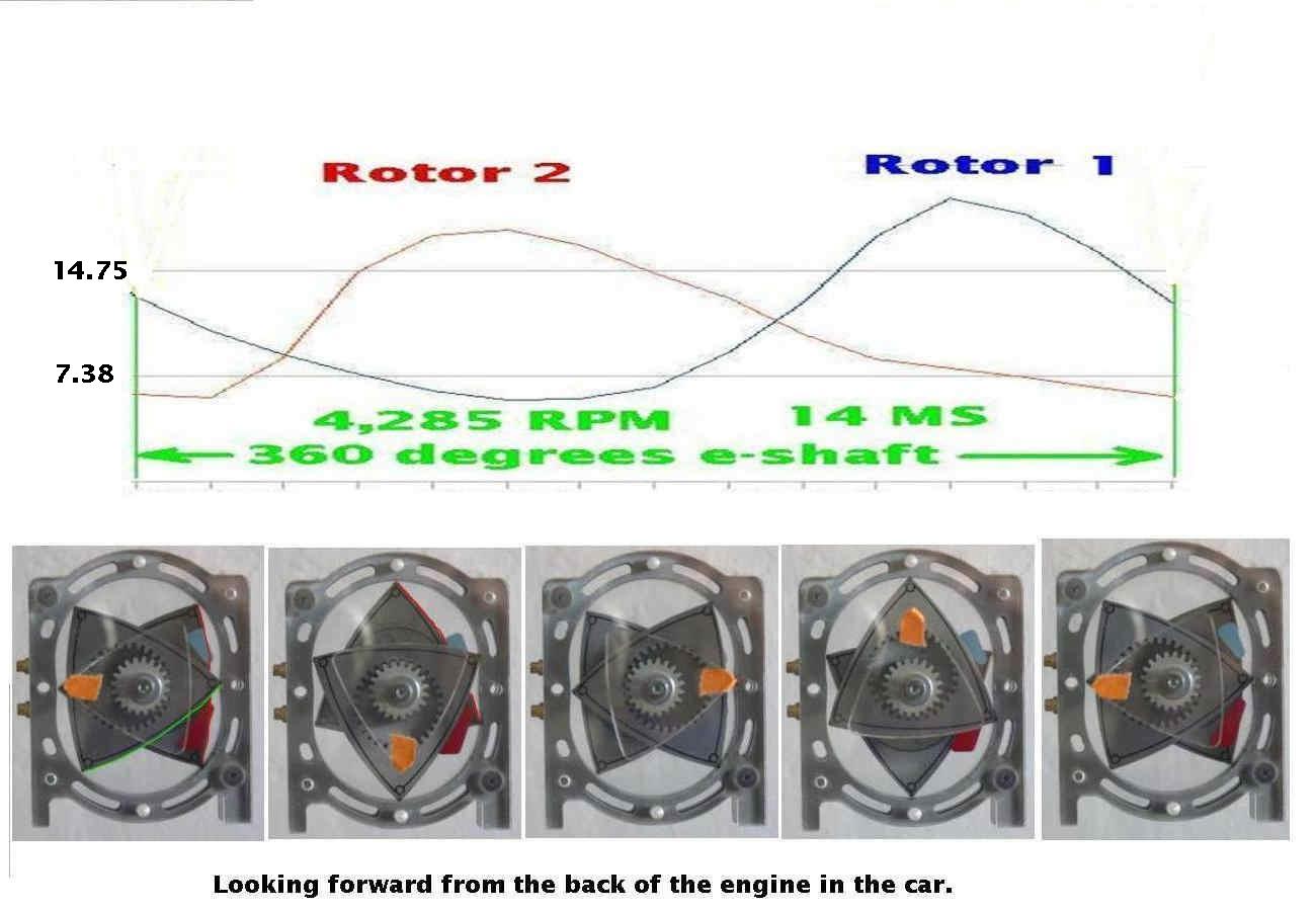
The flow does not stop at all. As the apex seal passes the intake port the
following chambers opens up to the intake port.
You need one of these transparent rotary engines to understand how it
works :)
Paul Lamar
--
The Rotary Engine NewsLetter. Powered by Linux.
ACRE NL web site.
http://www.rotaryeng.net
Youtube key word PaulLamar2
Copyright 1998-2011 All world wide rights reserved.