I have about decided to do a single chip solution to
the dwell ignition problem because potentially it is the
cheapest way to do a stand alone ignition for use with a carb.
The knowledge gained can then be used to do a variety of simple
things including a trim table adjustment to the 555 fuel injection
system using spread sheet data as suggested by Henry Nee.
I will focus on assembly language as these are time critical jobs
and with assembly language you always know how long
it takes to do anything. If you keep the job short and
simple the software size will be manageable from many aspects.
Further more I have considerable experience with assembly
language much of which can be applied to the AVR instruction
set.
I realize that most of you will not be interested so you
can delete the messages on the subject.
Those that wish to follow along can make a folder and move
the stuff over to that.
Tom Walter, I think, was the first to mention the
Arduino board as a good low cost and small AVR trainer that will
do a variety of jobs. The advantage is it is wired
for USB and there is programming software that runs
on both Windows and Linux.
There are a lot of people using this board around the world so there
should eventually be a lot of asm code examples.
The Arduino Mega 2560 is a small microcontroller board based on the
ATmega2560.
It has 54 digital input/output pins (of which 14 can be used as
PWM outputs), 16 analog inputs, 4 UARTs (hardware serial ports), a
16 MHz
crystal oscillator, a USB connection, a power jack, an ICSP header,
and a
reset button. It contains everything needed to support the
microcontroller;
simply connect it to a computer with a USB cable.
We will be using only a very few of these capabilities but the cost
and size is so low it does not matter.
AVRA is an assembler for Atmel AVR microcontrollers, and it is almost
compatible with Atmel's own assembler AVRASM32.
The initial version of AVRA was written by John Anders Haugum in
1999. He
released all versions until v0.7. All later versions were released
by Tobias
Weber. And version 1.3.0 is released by Jerry Jacobs.
Paul Lamar
Paul,
This will be fun to follow along. Not much out there for ASM for
Arduino since they use C for almost everything. I think the Arduino C
language has a function that can call ASM routines.
Bob G.
Here is one fragment I found. I'll comment it a bit to explain
what is going on. Feel free to correct me if I make a mistake.
.INCLUDE "M2560DEF.INC" ;this is a standard block of code stored on the HD
.equ RS = portb6 ; these are called equates and assign value or
.equ Enable = portb5 ; locations to labels. RS is the label.
.equ BusyFlag = porte4 ; the location is portb bit 6
........rjmp main ; this is jump instruction telling the processor to
; go to the "main" lable. Why the programer did this
; I have no idea. The code will go there anyway.
main:............... ; this is the "main" label. The assembler will assign an address in the mem
; when you say goto. You don't need an absolute address the code will
;know where to go when you say goto main:.
.......rcall init ; this is telling the CPU to go to a some code labled "init" and excute it.
; when "init" the code is done it will return back here and start executing
;right after this instruction.
init: .............. ; this is just the start of the routine. When it finishes it will ret.
rcall wait ; call "wait". a routine that waste a bunch of time.
sbi portb,6 ; set bit 6 in portb
ldi r16,0b0011_0000 ;load the the hex number 0b0011_0000 in register r16 I think.
out porte,r16 ; copy the number in r16 out on porte
sbi portb,5 ;Set Enable bit in portb, bit 5
-------------------------------------------------------------------------------
; This is called memory mapped input output. A I/O port looks just like a memory
;location. The assembler program reads the acii text in this file and translates it to
;a bunch of numbers stored in sequential memory locations. Each number is a code
;telling the processor what to do next.
;The semi colon means it is a comment and the asembler
;ignores all comments.
----------------------------------------------------------------------------
nop ; a no operation is used to change the length of time a routine
; takes to complete a job. This is one example how assembly
; language can easily add or control time of execution.
; IMHO not easy to do using the C program language.
; when controlling hardware time is of the essence.
-----------------------------------------------------------
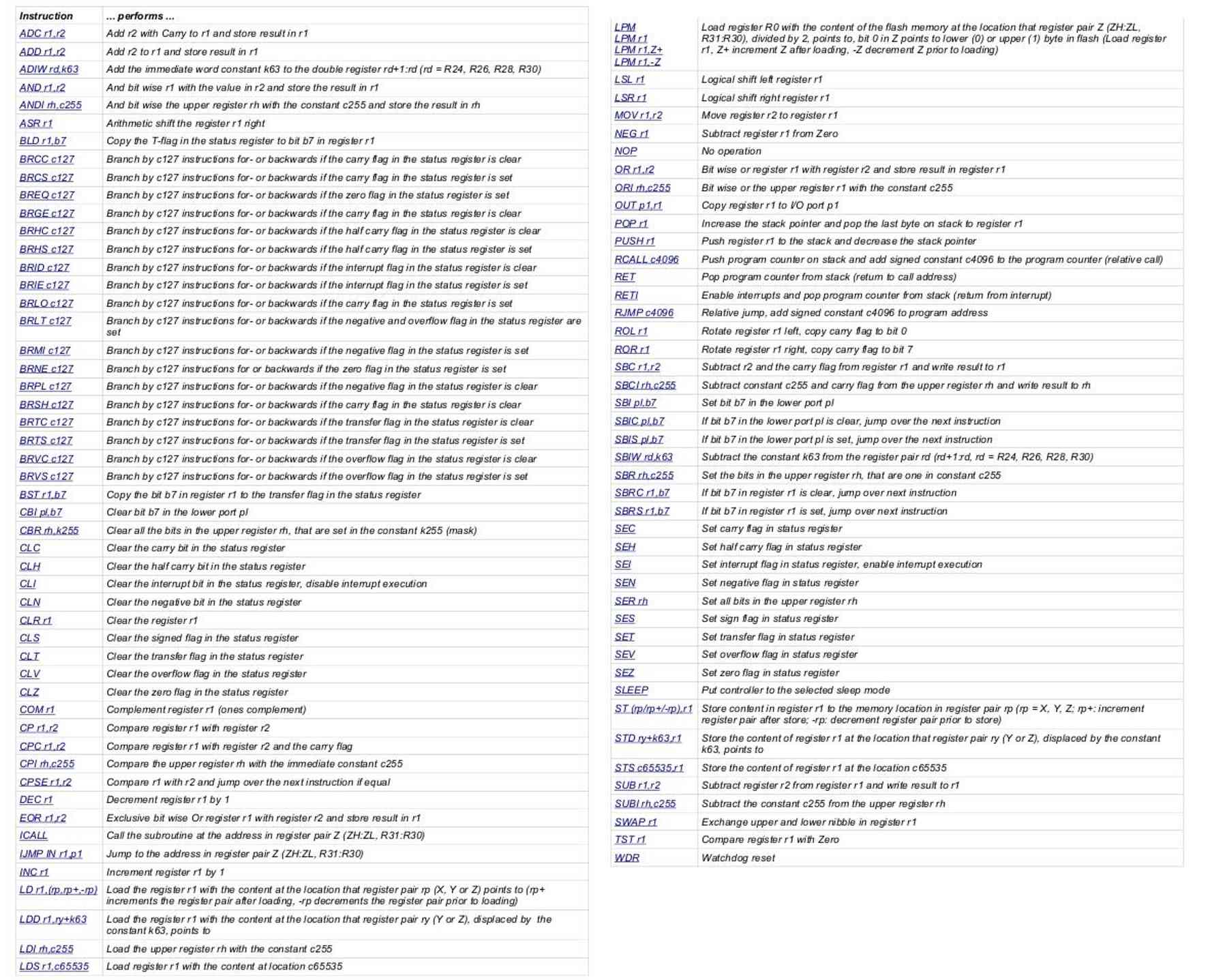
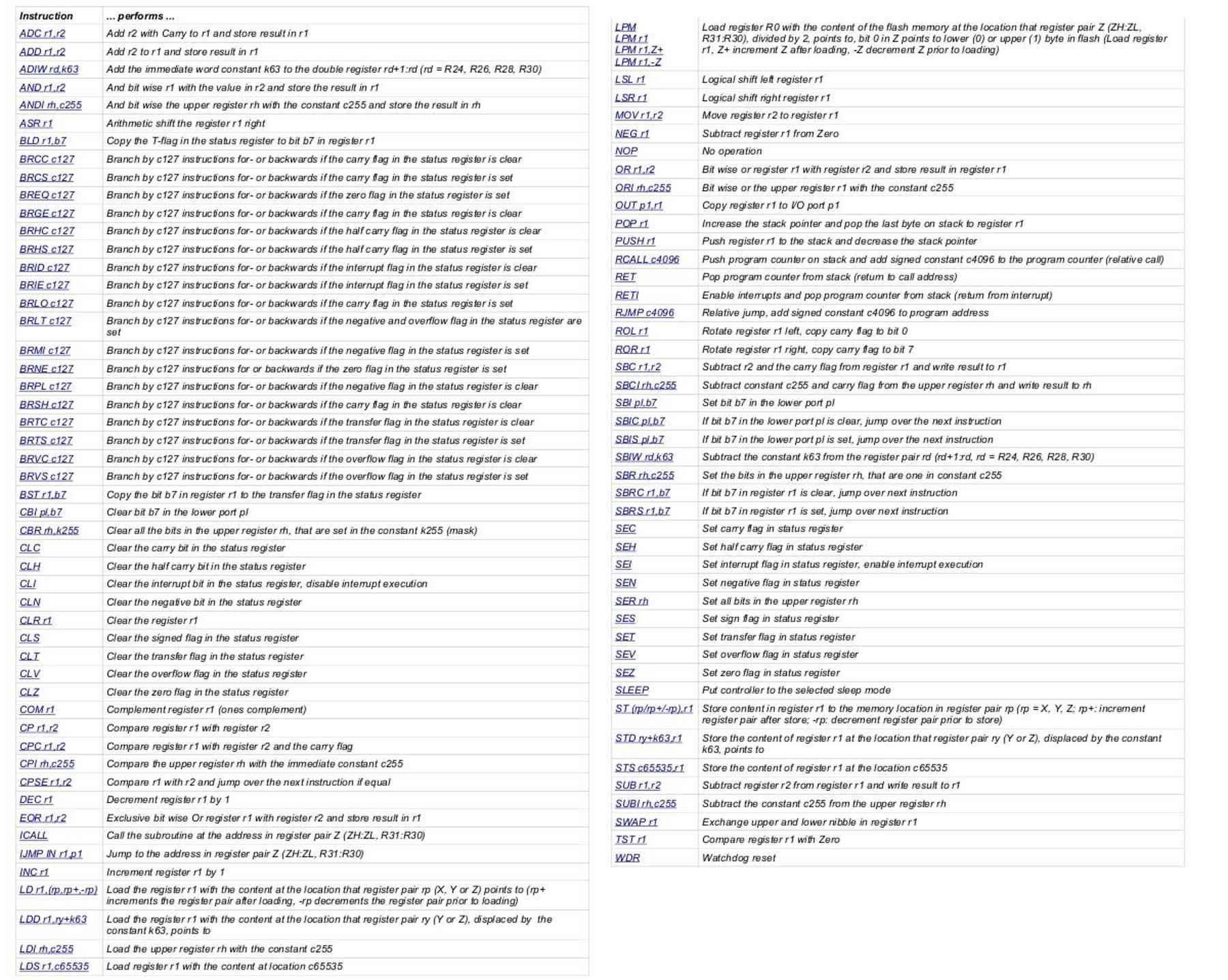
Here is a pdf of the complete list of instructions and what they do.
Hopefully you are now getting an idea of how all computers work.
This is down and dirty on exactly what computers do and how they do it.
It is very very simple. It is like a person standing in front
a huge storage cabinet with thousands of drawers while moving and copying
numbers around from drawer to drawer one step at a time.
Stuff falls out the back if it is an output drawer or port. If it is an input
drawer or port somebody is standing at the back side of the cabinet putting
stuff in the input ports. :)
The out put drawers or ports are merely 8 electrical switches that turns things
on and off. That's it. It is no more complicated than that.
---------------------------------------------------------------------------------
Assume the CAS signal is coming into location c65535.
We need to do something to adjust for the dwell delay.
.INCLUDE "M2560DEF.INC" ;this is a standard block of code stored on the HD
........rcall init ; this is telling the CPU to go to a some code labled "init" and excute it.
; when "init" the code is done it will return back here and start executing
;right after this instruction. init probably sets up all the options
;in the way and how the computer functions.
Not-CAS: ; this is called polling. One of several ways of detecting a bit change.
.........lds r1,c65535 ;Load register r1 with the content at location c65535
.........brlt 1 Not-CAS ; if it is not 1 go back to the label "Not-Cas" and do it again
It-is-CAS:
.......... ;Do something and then fire the ignition.
The polling loop executes in less than a usec so if the CAS pulse is wider than
one microsecond and it is.... this trick will detect it. The CAS pulse is on the
order of 100 microseconds or .1 ms.
Polling is probably the simplest of all the ways to check for a change in something.
Another example of the detailed time control available when you write in ASM.
Don't be intimated by the number of different instructions.
We will only be using half a dozen or maybe one dozen different
instruction to write our programs. The way it works is you
use what you know then... if you get to a hard place... you look
at the instructions and find one or more that does the job easier or
quicker.
Paul Lamar
--
The Rotary Engine NewsLetter. Powered by Linux.
ACRE NL web site.
http://www.rotaryeng.net
Youtube key word PaulLamar2
Copyright 1998-2011 All world wide rights reserved.