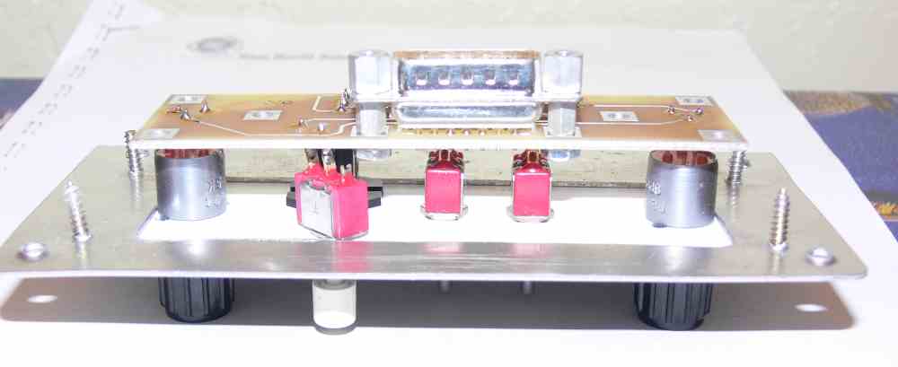
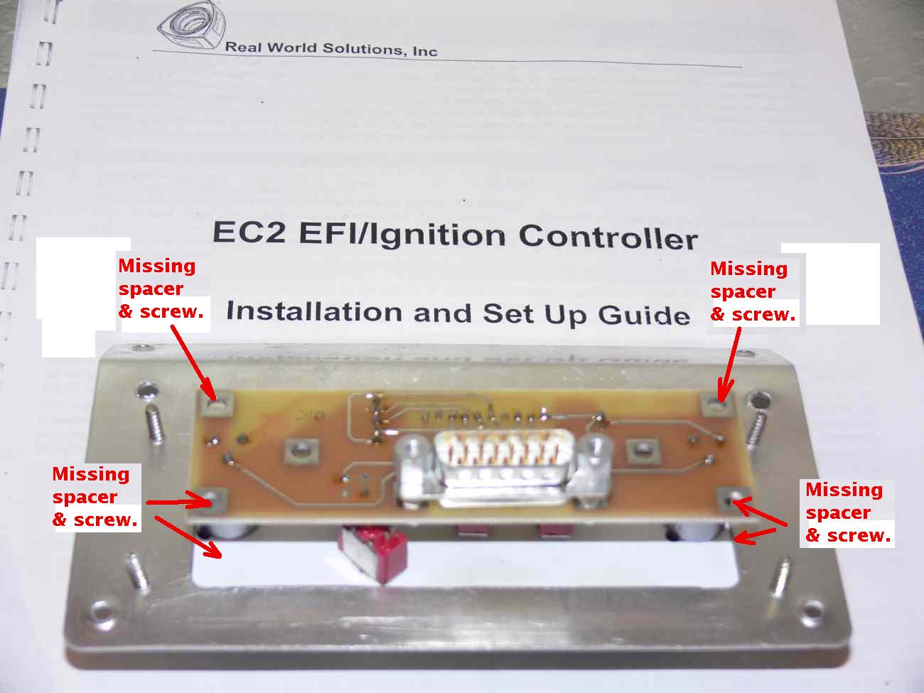
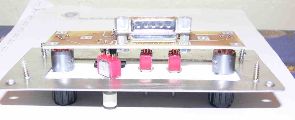
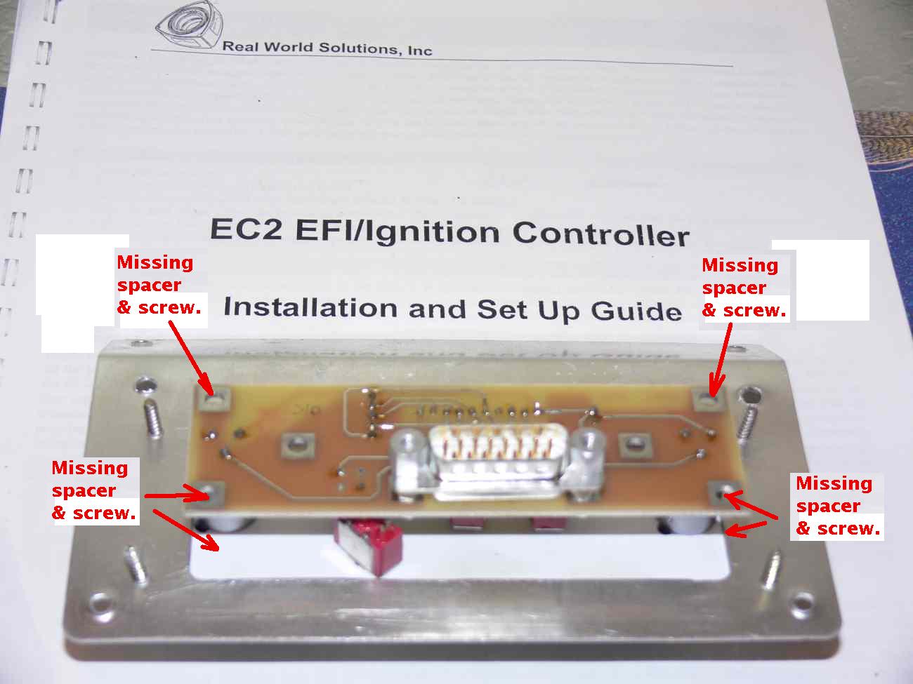
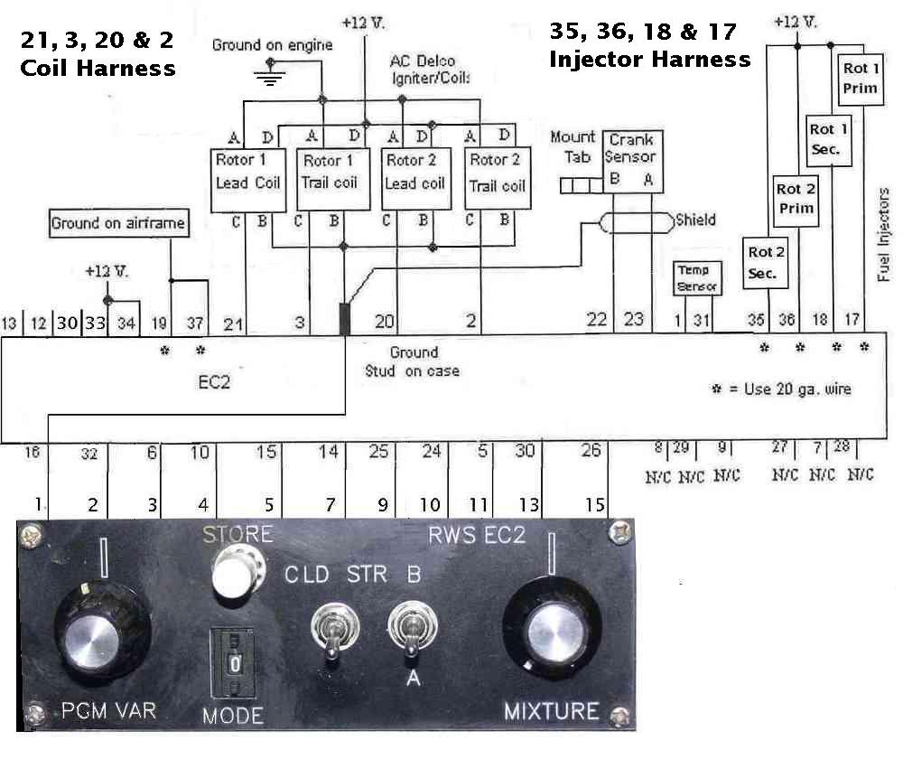
I had a solder connection failure on the unit as Mike did not
use spacers and long screws to mount it on the instrument
panel. He used only the front plastic panel.
Fortunately I caught this before I flew the RV4 again.
Mike had about 50 hours ground running and flying.
In some cases the flat head 6-32 screws will wind up partially
under the knobs and perhaps under the switch lock washers.
The reason it probably failed is the cantilevered weight of
the harness and DB15 connector off the back side of the unit.
That puts a strain on all the solder connections.
I am in the process redesigning the PCM to make it much smaller
and to fix this problem in the bargain. If you have a PCM
mounted only by the plastic PCM front panel I suggest adding
these spacers and long 6-32 screws to better support the PC
board.
Paul Lamar
--
The Rotary Engine NewsLetter. Powered by Linux.
ACRE NL web site.
http://www.rotaryeng.net
Youtube key word PaulLamar2
Copyright 1998-2011 All world wide rights reserved.