Since most solid state, so called gyros, if not all use a
capacitor
bridge circuit to sense acceleration and this is how they work.
The mass is seeing the one G acceleration force due to gavity
and is deflected downward. That means the spacing between
the plates
of C1 gets larger and the spacing of C2 gets smaller.
As the spacing of the plates of a capacitor get larger
the capacitance is reduced. When the spacing gets smaller
the capacitance is increased.
Think of a capacitor as a variable resisters for waves.
There is an oscillator that supplies a constant amplitude
sine wave to the device.
The amplitude of the wave coming out of this circuit will
then be proportional to the number of G's the mechanical
circuit is subjected
too.
Very high frequencies are used as these capacitors are tiny
to say the least.
The basic capacitance is on the order of only one pico farad.
The wave amplitude coming out can be rectified or converted
to DC and
then fed to an A to D for computer input. Use four of them
mounted equally spaced in a circle and you have a angular
rate sensor.
This is an extremely simple idea and it is easy to make.
One can make their own, in any shop, using nothing but hand
tools,
vastly scaled up from what one finds in a MEMS chip.
Paul Lamar
Paul,
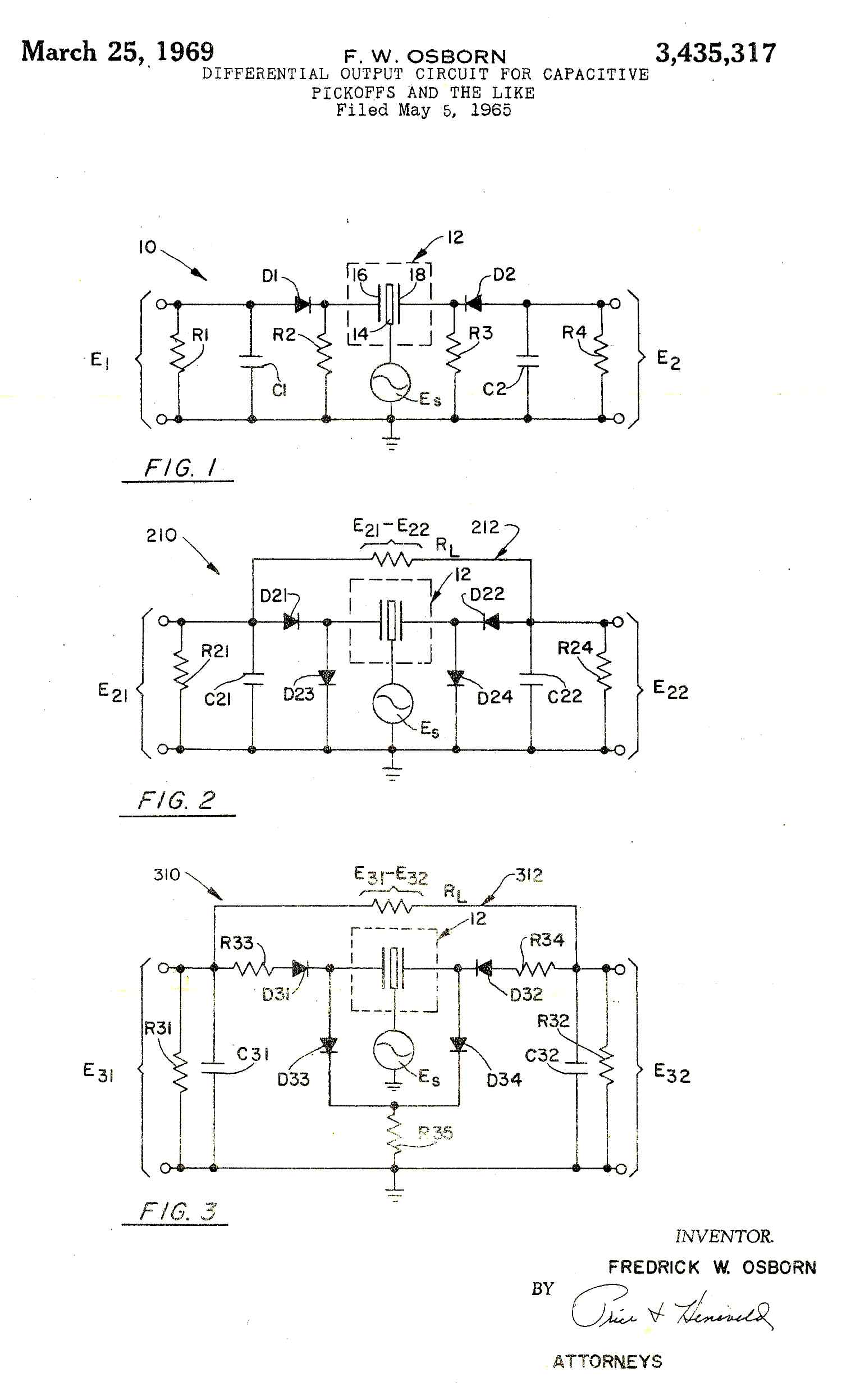
This thread took me on a little trip down memory lane, see
attachment. In 1965 I was doing circuit design for Lear,Inc
and supporting inertial instrument development when I came up
with this. I was pretty proud of it at the time, my first
patent, 1MHZ excitation, 1 uvolt/uinch displacement, with
relatively small plate areas, simple interface with a
differential opamp. Years later I stumbled on a book authored
by someone at MIT and realized that my patent probably should
not have been granted.
I hope the attachment comes through, its the best I could get
with my Mac and HP printer.
Fred O.
--
The Rotary Engine NewsLetter. Powered by Linux.
ACRE NL web site.
http://www.rotaryeng.net
Youtube key word PaulLamar2
Copyright 1998-2011 All world wide rights reserved.