bridge circuit to sense acceleration and this is how they work.
The mass is seeing the one G acceleration force due to gavity
and is deflected downward. That means the spacing between the plates
of C1 gets larger and the spacing of C2 gets smaller.
As the spacing of the plates of a capacitor get larger
the capacitance is reduced. When the spacing gets smaller
the capacitance is increased.
Think of a capacitor as a variable resisters for waves.
There is an oscillator that supplies a constant amplitude sine wave
to the
device.
The amplitude of the wave coming out of this circuit will
then be proportional to the number of G's the mechanical circuit is
subjected
too.
Very high frequencies are used as these capacitors are tiny to say the
least.
The basic capacitance is on the order of only one pico farad.
The wave amplitude coming out can be rectified or converted to DC and
then fed to an A to D for computer input. Use four of them
mounted equally spaced in a circle and you have a angular rate sensor.
This is an extremely simple idea and it is easy to make.
One can make their own, in any shop, using nothing but hand tools,
vastly scaled up from what one finds in a MEMS chip.
Paul Lamar
It seems that you are discounting the sensors based on vibrating beam
and
the Coriolis effect. Not sure why.. These are the sensors that
actually
act like gyroscopes.
http://m.sensorsmag.com/sensors/acceleration-vibration/an-overview-mems-iner
tial-sensing-technology-970
Regards,
Matt-
Again they are misusing the term "gyroscope" for marketing purposes
IMHO. A
real gyroscope is a 3D device. A change
in the Z axis of the real gyroscope results in a force in the X or Y
axis.
You get both roll and
pitch information from one device.
"As a result, the gyroscope[???] provides accurate angular rate
sensing for
rate changes from very small
to very large, with minimal errors from short- or long-term drift."
These are plainer devices hence they are angular rate sensors. It
takes two
and computer
integration to get roll and pitch information. The beam deflection
they are
talking about
here can be sensed by the same bridge capacitor electronics.
http://en.wikipedia.org/wiki/Coriolis_effect
"In physics, the Coriolis effect is a deflection of moving objects when
they
are viewed in a rotating reference frame. In a reference frame with
clockwise rotation, the deflection is to the left of the motion of the
object; in one with counter-clockwise rotation, the deflection is to
the
right."
Note: no mention is made of a 3D system.
Also they are not telling you how they sense the deflection of the
sensing
beam.
Paul Lamar
http://en.wikipedia.org/wiki/Vibrating_structure_gyroscope
Matt-
And:
http://en.wikipedia.org/wiki/Halteres
Matt-
Agree that a vibrating structure gyro is not an accelerometer. It
should measure absolute change in heading. It's closer to this:
http://en.wikipedia.org/wiki/Foucault_pendulum
-Chris
No I don't agree.
It is not a gyro!!!!!
A pendulum senses the vertical. Is it a gyro. Hell no!!!!
Paul Lamar
Those links explain it pretty well. A vibrating structure that is
vibrating in planes other than the vertical will display the same
effect. This effect is completely independent of gravity, however the
pendulum is simply a convenient way to illustrate it. Definitely not
an accelerometer. Functions like a gyro, though I can see why the term
is disputed.
-Chris
Hi, this seems useful:
http://electronicdesign.com/article/analog-and-mixed-signal/This-Year-s-Best
-Analog-Design-Will-Find-You-In-The-Dark.aspx?cid=ed_powernewsletter&NL=1&YM
_RID=
Murry I Rozansky
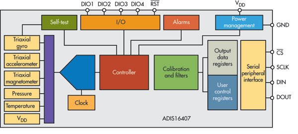
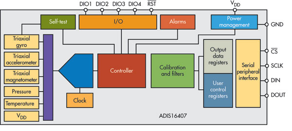
"In June, Analog Devices released the ADIS16407 iSensor inertial measurement
unit (IMU), which integrates a tri-axis gyroscope, tri-axis accelerometer,
tri-axis magnetometer, and pressure sensor, with associated signal
conditioning, in a single package (Fig. 1). That’s 10 degrees of freedom.
Every IMU is factory-calibrated for sensitivity, bias, alignment, and
temperature. Each sensor has its own dynamic compensation formulas,
maximizing accuracy of sensor measurements."
"The pressure sensor and the tri-axis magnetometer, which adds the ability to
sense the Earth’s magnetic field relative to the device, is the major
advance over the company’s ADIS16334, increasing the degrees of freedom from
six to 10."
"Navigation technology used in first responder or unmanned vehicles not only
requires multiple axes of sensing, precisely aligned, but also
cross-integrated to discern tracking/location in dynamic environments,” says
Bob Scannell, business development manager at Analog Devices. “Where no one
single sensor provides the required precision, the solution involves merging
multiple sensor types with a deep knowledge of the dynamics of the
application environment."
--
The Rotary Engine NewsLetter. Powered by Linux.
ACRE NL web site.
http://www.rotaryeng.net
Youtube key word PaulLamar2
Copyright 1998-2011 All world wide rights reserved.