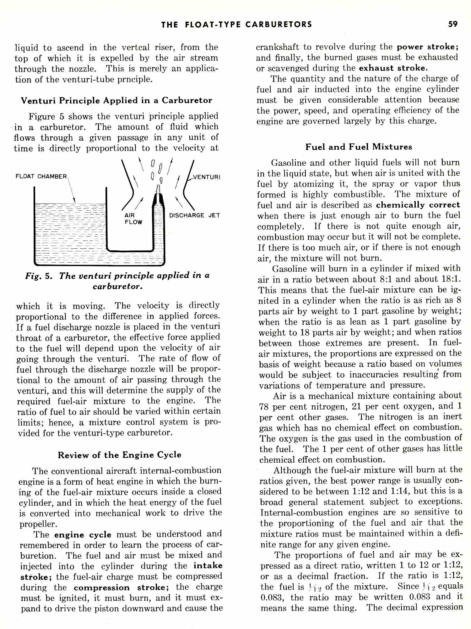
Here are some of the latest 3D's showing how the float
bowl moves up and down a half inch to lean the mixture.
The scale on this DWG is more accurate as I found
my Holley 4 barrel to measure.
BTW if you apply dynamic pressure to the float bowl
the delivered mixture will be a function of both vacuum
in the venturi throat plus the square law dynamic pressure
In other words the dynamic pressure in the
intake runners will be the square of the air velocity.
At full chat that can be as high as 300 MPH.
Sort of a mini pito tube in the intake runner.
I am not sure this is what you want but it can always
be leaned and the bottom line is: the fuel will squirt
out into the intake runner better.
I learned this trick from Ellison.
The more I work on this the better it looks.
You will be up and running in 5 minutes not
one year tuning an EFI in the air.
There are only four cheap parts to make.
The rest of the needed parts are stock Holley.
One can buy a brand new 4 barrel Holley for $250 to scavenge
the parts from. Perhaps someone can find some on ebay.
Paul Lamar
Here is a more compact version that will fit under most
cowls.
Paul Lamar
Paul,
The 2 float bowls could be mounted to a single metering plate cross
drilled with 2 separate outlets. Then only one unit would have to be
raised and lowered. Would this require flex tubing from the bowl
outlets to the venturi tubes? We would have to turn a venturi into 2 2
inch OD tubes? Just thinking.
Joe Berki
It does require flex tubing. Each float bowl needs to be close
to the jet. Sketch up what you have in mind.
Here are some dwgs for the Marvel Schribler HA-6
Paul Lamar
Paul,
Here is a sketch, I am not sure if there are any other connections to
the system. Please elaborate.
Joe Berki
Limo EZ
Nice sketch Joe but you must draw things to scale. Won't fit. The float
bowl is too long. It must go between the tubes to get the float level
high enough. That is why a 3D program like Rhino is worth its weight in
gold.
Paul Lamar
Paul,
One thing that I notice is that when you draw an intake you wrap it over
the top of the block which probably the best way to design it as it goes
to the cold side of the engine. I do not have that option and will
route the runners straight out and downward placing any plenums,
injectors or other intake components in the wing root aft of the spar.
I can also spread the runners apart. The bowl sandwich could be turned
90 degrees and perhaps take up less space. Could you go through the
principle of how this works? Does the bowl have to be able to travel
lower than the venturi point? Does this raising and lowering of the
bowl cause the amount of fuel to vary? Does it change the pulling
potential of the low pressure in the venturi? The needle valve is the
same at both points and the fuel level in the bowlis the same. i am an
electrical type not mechanical although building a plane is a great
education in all things mechanical.
Thanks for any help
Joe Berki
Limo EZ
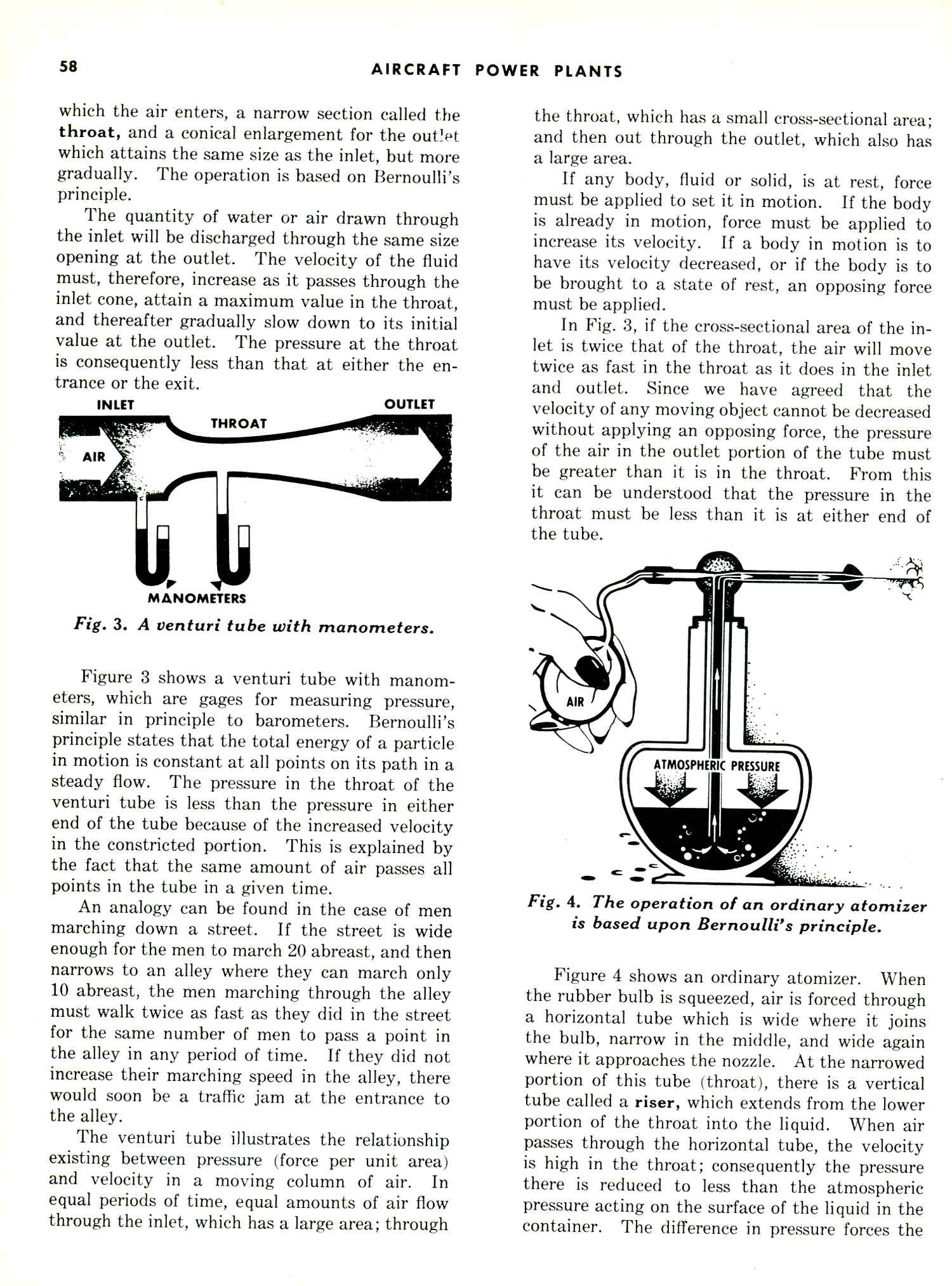
It is a close kin to a U tube manometer.
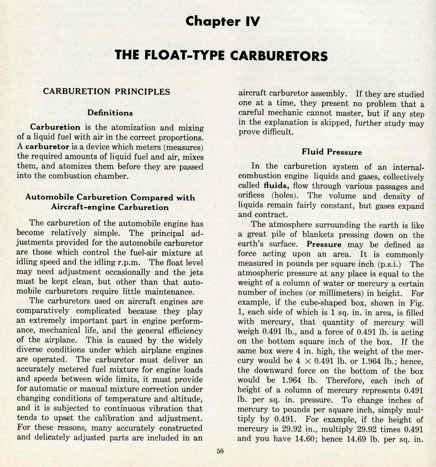
Here is a good dissertation.