There is almost no perceivable space in the bores at idle setting.I
agree with the suggestion of drilling 3 small holes (one per
runner) in the slide. I had considered doing that to help during
idle.
As for the air leak... During idle, the 2" hole in the Teflon
slide for rotor #1 moves very close to the hole in the frame for
the cable. This could provide a path for the air to bleed into
the #1 rotor causing it to run lean. This may account for the
higher
than normal MAP as well as a mismatch in air-fuel mixture during
idle. It would become less of an issue as the throttle is opened,
exactly as I am experiencing. I suppose I've got it tuned as
well as possible, but with this condition, I don't see how I
will ever
get it to run well at low MAP. It shouldn't be too difficult to
install a small seal. It sure wouldn't hurt anything. I could
probably stuff a small piece of shop towel around the shaft for a
down-and-dirty test. If the idle improves I'll know that I'm on
to something.
Mark S.
A seal would be worth a try in that case.
For future use do you have room to make the slide an inch or so
longer?
Paul Lamar
Paul,
I guess it is possible (anything is possible), but not really
practical.
Ref. *Marks pics 2009-2010 287.JPG *showing how close to the firewall
it is now. The other end is up against the oil cooler. So, what did
you have in mind?
Mark
One inch longer on the fire wall end.
But try the seal first.
Do you have Teflon on both sides of the slide?
That should help seal the top and bottom in case it is leaking
around the edges. Also what is the exact gap at idle?
I can figure out the area.
Paul Lamar
Paul,
I'll try to measure the gap on my next trip to the airport, which
willbe next weekend.
Previously, I had sealed around the edges with Hylomar. I also added
more screws around the perimeter. I had it apart last weekend to
addan idle stop (should have done that in the beginning). I
didn't haveany Hylomar on hand, so I reassembled without it.
That may becontributing to the current problems.
Do you recall that originally my Teflon slide had way too much
friction, so I added a sheet of .032" Teflon on the downstream
side. Well, this stuff flows over time allowing tolerances to
change. I've ordered a sheet of .032" high temp Garolite (G-7).
This should provide a slick surface for the Teflon to slide plus be
more stabe structurally.
I only plan to make one change at a time so I will know what
helps andwhat doesn't.
My concern with the "Holley float bowl" idea is that every Holley
carbI've ever owned has leaked fuel sooner or later. With the intake
located directly over the hot exhaust, I would not be comfortable
withthat. It would definitely need a catch tray.
Mark
OK NOW I remember. You have a REAL teflon slide.
There were or are two different tolerances for sheet
Teflon. The lower cost of the two had very lax tolerances
on the thickness. Perhaps plus .0032. and minus .015".
A 12 by 24 sheet cost only $90 :)
That would explain the high force.
Since you added the spacer to give more clearance to reduce the
force that would also lead to many air leaks in and around the inside
of the slide throttle. Take that thick Teflon slide out of there
and replace it with 1/4 inch thick aluminum plate and thin .032
Teflon liners. This also makes a much cheaper slide throttle as
all that
Teflon
is expensive. The precision ground blanks stuff is about $250 for
a 12by 24 sheet 1/4 inch thick. 3/8th thick would be $385. Tol is
+/-.005.
As per these pictures. Note the aluminum slide in the slide
throttle kit picture. The tolerance on aluminum sheet is probably
closer
to plus or minus .001. Thanks to C. Smith for these pictures.
Don't do the Garolite thing. It is useless as a gasket.
1/32 thiick Teflon is better. The tolerance on the cheap
1/32 stuff is +/- .003 and a 12 by 24 sheet is only $12.
For years Mazda rotaries had 4 barrel carbs mounted directly
over a thermal reactor to reduce unburned Hc. For some strange
reason they did not catch fire. I am not sure if it was too lean
ortoo rich. My guess is the fuel falling on the red hot reactor would
vaporise instantaneously. It seemed to me that would be an
explosive mixture but it never seemed to happen.
The RX2 had a tray under the carb. Here is a picture.
Paul Lamar
Paul,
The piece of Teflon that I had added was not to take up any gaps, but
was to create a Teflon-to-Teflon sliding surface. And it worked very
well, except that Teflon flows and deforms over time. You could
see Teflon oozing from between the layers of aluminum where the
screws are located. Recently, when I took it apart, there were
three "bulges" where the slider holes are positioned when the
throttle is closed. I recently took an Xacto knife and removed
the bulges, which may have exacerbated the vacuum leak. I don't
see how making the slide from aluminum would resolve either of
these two issues.
On a side note, when I first added the Teflon sheet, I also removed
some material along the top of the Teflon slide, but left a small
bump on each end to keep it in place. My thought here was that when
heated, the Teflon slider was expanding enough to cause binding onthe
aluminum frame top and bottom. This may have helped more to relieve
binding than the additional sheet of Teflon. Maybe I should try
removing the Teflon sheet completely.
I've also considered making the downstream plate from SS as this
would reduce the COF without the material problems associated
withteflon.
Machining is the only issue I can see with the SS sideplate, but Bob
Darrah can handle that for me.
Mark
I am not following you Mark. Are you saying the 1/4 inch thick
Teflon slider is bulging into the the 2 inch intake holes?
Can you send me a sketch?
Coefficient of Linear Thermal Expansion for Teflon
(x 10-5 in./in./°F) 7.5
That is ( I think) 0.000075 inches per inch per degree F.
At 100F that is 0.0075 or 7 thou per inch.
At 2 inches wide would be 2.015 or fifteen thou wider.
6061 aluminum is 13 micro inches per inch per degree F
A micro inches is .000001 inch
So it is .000013 inches per inch per degree F.
So at 100 F that 0.0013 per inch. 2 inches is only 0.0026
wider. Not much difference. You must have cut that Teflon
exactly. Did Bob machine it?
I guess that looks possible unless I am making a mistake
here.
Mic your Teflon slide in a few places and see how uniform
it is.
Paul Lamar
Paul,
For clarification, the .032" Teflon is what deformed over a period
of a year or so. There were three bumps where the holes in the
teflon
slider rested when at idle or stopped.
Also, the .032" Teflon (which was captured between the frame and
the downstream side plate) squished out at each screw location.
This has caused the downstream aluminum plate to deform. As a
result, I don't feel that Teflon is a good material to use here.
Keep in mind that the slider gets sucked towards the downstream
plate, especially at low MAP settings.
Also, the Teflon slider is .380" +/-.
Mark
The thickness tolerance on 3/8 Teflon is +.038" and minus .019".
That is a bunch. Lots of room for leaks between ports.
My theory is the non uniform thickness of the Teflon slide is
allowing air to leak from port to port. The intake surge or intake
pulse is 120
degrees out of phase for a 3 rotor. All sorts of weird things
can be happening in there. You will see that when you get it
instrumented with the high speed pressure sensors.
I still say dump the Teflon slide and replace it with uniform
thickness aluminum slide.
OK maybe we need the etched (bondable) on one side .032 Teflon and
epoxy it down to the aluminum covers. Better yet you can also buy
that in .015" +/- .002" thickness. Less chance for cold flow.
Either anodize the covers first or get the aluminum etching kit
from a boat supply shop. Here is a jpg of the etching stuff you
will need.
Teflon is the only material that provides the needed low
coefficient of friction.
What is the thickness of the downstream aluminum plate?
You can make a doubler out of .25" thick aluminum
1/2 inch wide bars to spread the clamping loads from the 10-32
screws. That is a common problem in oil pan bolts. McMaster sells
aluminum bar stock in that size (1/4" thick 1/2" wide) for about $8
bucks for 8 feet long.
I will change the slide throttle instructions to include those
improvements. I really appreciate all the long term R&D you are
doing on this Mark. You are a real pioneer.
Paul Lamar
Paul,
I like the idea of bonding the .015" Teflon to the covers. I may
give that a try after sealing off the big leak around the cable.
Another thing that I found that I haven't mentioned is the .032"
teflon
had puckered around a portion of the #3 port to where it may have
interfered with the slider closing completely. This was only seen
on one port and may have been caused by a sharp edge. Anyway, as
I said earlier, I remedied this by cutting away some of the teflon.
I had another idea to reduce friction. Could it be built with a
little
excess clearance between the slide and the two sides and then use
Teflon o-rings to provide a seal around each port. The o-ring
would have to be racetrack-shaped so as to not catch or snag as
I've described above.
The o-ring groove could be made with a wood router using a guide
block.This would make for minimal surface tension between the slider
and side plates.
Mark
I figured out why you are getting .032 Teflon bulges in the area
you are talking about. I looked in an old book I had on aircraft
carbs
called "Aircraft Power Plants" published by Northrop Aeronautical
Institute back in 1948. It has an excellent chapter on carburetters
theory and practice. It reminded me at idle the air velocity is
very high in the area of the slide throttle that is still open
during idle. More importantly the air pressure is also very low.
That has sucked the Teflon away from the metal cover. Therefore
bonding it to the metal is essential.
Here is some scans from that book.
IMHO you don't need the O-rings if the slide is close tolerance.
If the edges of the slide catch one and drag it out of it's
slot it could be disastrous.
Here is Mark's slide throttle p-port 3 rotor engine for the new guys.
Paul Lamar
Can we get an aluminum throttle plate coated in Teflon, just like a
non-stick skillet? Should have very uniform thickness. You can buy
a Teflon coated skillet for less than $10, so it shouldn't be an
expensive process.
Regards,
Matt-
Make a large single bore slide with one skillet cut up. Price is
right. Use
Teflon buttons and springs to push the "cooking surface" to the
engine side to keep seal. Install upstream of the injectors.
Dale Davies
We already have a bunch of 2 rotor versions made. It is cheaper
to epoxy on the .015 Teflon. Goto
http://www.rotaryeng.net and
scroll down to the bottom of the front page.
The .015 Teflon acts as a gasket at top and bottom
to seal the over all slide assembly.
I might point out for people the reason we went to the aluminum
slide was the $100 cost of the solid 3/8 thick Teflon material.
This cost is much higher for a 3 rotor due to the length
of the slide.
One can buy it cheaper but the relaxed thickness tolerance
+/- .018 would force us to surface finish every slide in the NC mill.
It is called mechanical grade PTFE in the McMaster catalog.
Also Teflon is hard to hold down under these circumstances.
------------------------------______--------------------------__--__--__-------
Just got around to the finishing touches. Here are some pics. Brad
point
drill to prevent split from bolt hole, clamp between plates to
support sheets. Improvised punch from 2" copper pipe, would work
better pressed between 2 pieces of wood in a vise, but I finished
the cuts with an x-acto knife. 2" professional gasket punch is an
arm and a leg. 6 Bearing buttons on sides of slide keep alignment.
Cool Craig. I'll use these in an how to. Thanks.
Where did you get the Teflon buttons on the edge of the slide?
Made them from .187" (3/16") Teflon rod, available at scientific
commodities.
http://www.scicominc.com/______teflon_solid_rod.htm
<http://www.scicominc.com/____teflon_solid_rod.htm>
<
http://www.scicominc.com/____teflon_solid_rod.htm
<http://www.scicominc.com/__teflon_solid_rod.htm>>
<
http://www.scicominc.com/____teflon_solid_rod.htm
<http://www.scicominc.com/__teflon_solid_rod.htm>
<
http://www.scicominc.com/__teflon_solid_rod.htm
<http://www.scicominc.com/teflon_solid_rod.htm>>
Craig Smith
------------------------------______--------------------------__--
Paul Lamar
With regard to idle roughness; look at the website article on the
Le Mans
26B. Page 7 of 11 has a chart on air funnel and P-port injection
with regard to misfires.
Dale Davies
The side exhaust p-port intake RX8 engine idles very well.
Unfortunately Mazda never made a side exhaust port 3 rotor :)
Paul Lamar
Paul,
Thought I would post an update to my MAP/slide throttle issue.
I pulled it off the engine and installed the seal around the throttle
shaft using a 3/8" spot facing bitt. Then drilled/tapped an 8-32
near the hole for a retainer screw to hold the seal in place.
I also replaced the 1/32" teflon with the 1/32" garloc sheet (cut to
size with three 2" holes).
I matched the three holes in the slide so the air gaps matched at
idle setting. Not sure why this wasn't "right on" because all holes
were drilled/bored on a Bridgeport mill. Using a triangular file, I
filed a notch in each of the three holes in the teflon slide. This
was in lieu of drilling three small round holes as previously
discussed.
I reassembled the slide throttle using Permatex anerobic gasket
sealer.
After reassembly, the actuation force was noticeably lighter,
similar
to what you would expect with a typical carburetor or throttle body.
So, this aspect of the re-work was determined a success.
The test run revealed a much smoother idle around 1900 - 2000 rpm.
Throttle response was also much improved. Most of the off-idle
stumble was now gone. A little adjusting (leaning) of the MAP table
and it was running even smoother yet. A quick taxi test confirmed a
much smoother running engine. While not quite as smooth as my
original side port engine (it would idle smoothly at 1500 rpm), I
feel it is now an acceptable compromise.
So, I just wanted to say thanks for helping me sort out this issue.
Mark
Mark,
Where did you file the notches, on the bottom or the side?
Dale Davies
Dale,
The small v-notches were added at the 3 o'clock position (looking into
the inlets).
I went ahead and tried the garloc material as I had ordered earlier in
the week from McMaster and had it on hand. I did a quick bench test of
sliding the Teflon across the garloc, as compared to Teflon-on-Teflon,
and I couldn't tell any difference in COF between the two.
By the way Paul, I checked the dimensions of the Teflon slider and it
was between .362" and .367".
My question now is would the idle be even smoother if the primary
injectors were placed downstream of the slide? It looks like that is
how Mazda did their 26B LeMans engine. However, I doubt I'll try this
anytime soon. For now, I plan to just put some hours on it.
Mark
You lucked out on that. Almost sounds like you got the precision stuff.
Do you remember what you payed for it? Perhaps it is a sheet to
sheet tolerance. However .362" is a long way from 3/8th or .375".
How thick is
your spacer? If it is .375" you have a lot of leakage from port to
port and to the throttle cable. Our kits are .250" thick spacer and
.250" thick slide.
Injector position was an issue of throttle response and not idle. A
road racing engine must come on from 6000 RPM in a small fraction of
a second. During the race it never gets below 6000 RPM.
The main problem with idle in a double p-port engine (both exhaust
and intake) is mixture contamination with exhaust gases. The P-port
RX8 side exhaust port engine idles very well. Basically the same as
a side intake 13B.
BTW I updated
http://www.rotaryeng.net/__slide-throttle.html
<http://www.rotaryeng.net/slide-throttle.html>
with the bonded .015" thick Teflon slide surfaces. That should solve
both the bulge problem and the cold flow around the screws.
Paul Lamar
Paul,
Well, like I said, I'm pretty happy with the low speed operation now.
One thing that I did notice was that throttle response is much
improved. Heck, I wish my car's engine revved like this one does. So,
that isn't a concern.
I measured the Teflon slide _cold._ It may be a few thou. thicker when
heated. I didn't check the thickness of the spacer, but I am sure it
started out as 3/8" material. I don't recall if we took a cut across it
or not. My gut says that we didn't. But experience says that at low
MAP, the slide gets sucked against the downstream side plate. So any
gap would be on the upstream side. Anything upstream of the slide is
cross-connected via the common plenum. I'll be able to measure the MAP
for each individual rotor once I get my Hytech data logger. That should
tell me exactly what's going on.
Mark S.
Cross connected where ? :) There is 120 degrees between pressure pulses
on a three rotor of course.
Your results far exceeded my expectations. Double p-ports are supposedly
horrible below 5000 RPM according to certain racing people that have
built many engines. They did not have a 73 inch prop/flywheel however.
I was thinking we might need to idle the double p-port at 3000 RPM. Of
course the prop would be turning only 1000 RPM. My RX8 idles at 2000 RPM
until it warms up and then idles about 600 RPM with nary a miss.
I want to thank you once again for all the R&D you have done on this
and the welded p-port as well. Finding the bulge in the Teflon IMHO is
very important even thou it worked for a year. Stuff like this just
indicates how tolerant the rotary engine is of minor design errors. Dave
Leonard flew his airplane for many hours before a gear box oiling
problem showed up at Reno when he was really pushing it to go 229 MPH.
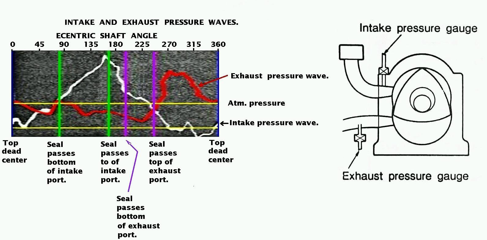
I am extremely curious about what is going on in the p-port slide
throttle intake manifold at low RPM's. Mark Suspinski's double p-port
powered Mustang II was crashed before we got a chance to gather pressure
data at low speed. The crash had nothing to do with the engine. We have
plenty of data at 5000 RPM and up. We never got any pressure data at low
idle RPM's. Perhaps you can weld some steel brake line tubing into the
exhaust pipes close to the engine and get some data there as well. That
should tell us which direction the gases are flowing when.
Paul Lamar