On a different topic, could you please send me a schematic of how to
wire the Hytek to the three pressure sensors?
Mark S.
OK what you need is a five volt supply.
There is a 3 pin chip called a voltage regulator. You put in any DC
voltage up to about 15 volts and it puts out 5 volts DC. You need a
diode in case you wire it wrong and a couple of caps to filter out
any noise. Enclosed is a schematic.
Then wire the pressure sensors as shown to the Hytek data acq.
You can use up to 8 pressure sensors numbered A0 to A7.
There are three active pins. One is 5 volts another is ground and the
third is the analog output signal zero to 5 volts proportional to
absolute press. Zero volts is zero inches of mercury and 5 volts
is 29 inches of Hg or 15 psi.
If you want to see what Tracy's sensors are telling the computer you can
open up the EC2 and connect Tracy's sensors directly to the data acq
using Tracy's 5 volts.
Paul Lamar
Here is some more stuff. If you want timing signals in your capture
file you need to use the HyTek Dx input signals. Those are events
like ignition coil triggers and injectors switched on.
It is probably a good idea to use opto isolators for that kind of stuff.
An opto isolator is merely a LED and a photo Tx.
It is mandatory to use them with injector driver and CAS as they
switch as much as 12 volts which will damage the HyTek.
"A simple reason? You could use an opto isolator if you were
uncertain about what you are doing. If you weren't sure that
circuits you wanted to connect to an input were "safe" for your
relatively expensive microprocessor, you could connect the
microprocessor to the opto isolator as above, and use your circuit
to turn the LED on and off. If you did that, then many mistakes you
could make would only ruin the quite cheap opto isolator. The Bad
Stuff won't jump across the gap between the LED and the
photo-transistor. If you've used a socket for the opto isolator
chip, always a good idea, then replacing it only takes a moment."
http://www.arunet.co.uk/______tkboyd/ec/ec1optoiso.htm
<
http://www.arunet.co.uk/____tkboyd/ec/ec1optoiso.htm
<
http://www.arunet.co.uk/____tkboyd/ec/ec1optoiso.htm
<
http://www.arunet.co.uk/__tkboyd/ec/ec1optoiso.htm
<
http://www.arunet.co.uk/____tkboyd/ec/ec1optoiso.htm
<
http://www.arunet.co.uk/__tkboyd/ec/ec1optoiso.htm
<
http://www.arunet.co.uk/__tkboyd/ec/ec1optoiso.htm
<
http://www.arunet.co.uk/tkboyd/ec/ec1optoiso.htm
As far as injectors are concerned you can feed the 5 volts output of
the opto to one of the analog inputs and it will automatically
record the width of the injector pulse.
It sure would be interesting to find out exactly what e-shaft angle
Tracy is firing the injectors.
Paul Lamar
Paul,
I've already got a 5v DC power source. So, I'm good there.
Do I
_need_ an opto isolator in order to capture MAP data, or can the
Hytek s/w do a sample of say 10 to 20 seconds. I would like to keep
this as simple as possible, at least in the beginning. I can always
add more capabilities later on.
On a side note, Bobby Hughes and myself spent a couple of hours on
Sunday re-tuning my EC-2. It idles pretty good now down
[p-port-3-rotor] as low as 1800 rpm, and most of the hick-ups and
stumbles are gone as well. The ones that remain are much less
significant. So, it was a fruitful day. We still need to tune the
portion of the MAP table that you can only get to while flying, and
the weather is IFR right now, so that will have to wait.
Mark
No you don't need the opto's for manifold pressure. Just hook those
little five volt jewels up directly as in this picture. The info
will be stored in comma delimited form (.csv) for import to a spread
sheet file.
Here are a few examples. The screen shot of run 6 xls spread sheet shows
some of the recorded data taken at 1000 samples per second.
The engine was running for 35,000 seconds or so at this point.
The column on the left shows the number of milliseconds at the point
where the data was taken. Unless you want huge 15 meg spread sheets
put an on and off switch so you can record data only when you need it.
This is a VERY powerful tool for studying intake manifolds.
There is also a spread sheet plot of the raw data in this attached
screen shot.
The big advantage of monitoring the injectors is you have a file on hard
disk of your curent tuning. Other people can do the same thing and
then a direct comparison can be made. If somebody is having trouble
they can compare their mixture settings with yours. This is a
powerful tool for tuning Tracy's system. I can also store these and
send them out to people with similar airplanes.
Paul Lamar
Paul,
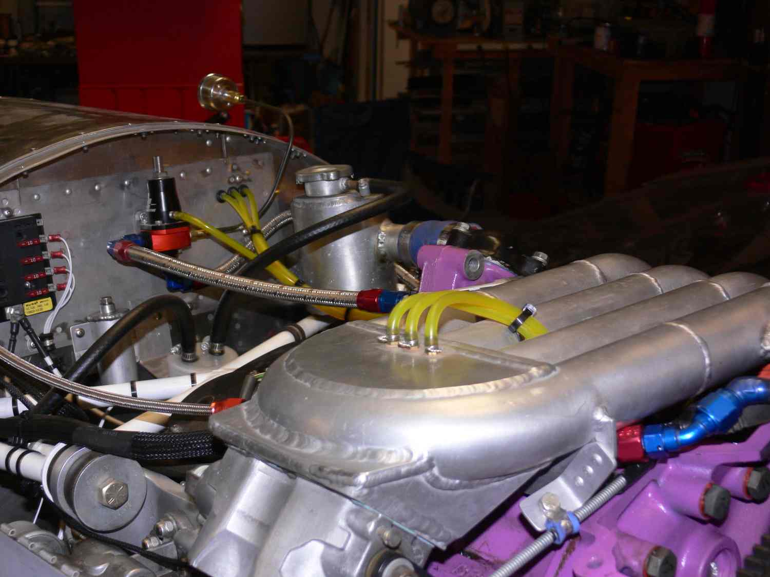
I'm anxious to get it wired up and start logging data. I envision using
a tee on each of the three rotors' vacuum ports. Since all three ports
are tee'd into one line, will I need check valves to isolate the pulses?
Mark
I would use 3 pressure sensors. One for each port. Then you really know
what is going on. If you get big leak in the throttle cable
end you will see a different wave shape for that port. I am thinking
of doing a PC board to hook the Hytek to at least 3 pressure
sensors, the CAS, All six injectors and all six ignition trans formers.
It will be equipped with opto isolators where needed and a 5 volt
power supply.
What do you think?
Paul Lamar
Suggest you include fuel pressure too. I'll take one.
Mark
I am working on the PC board as we speak.
Why fuel pressure? It is supposed to be constant.
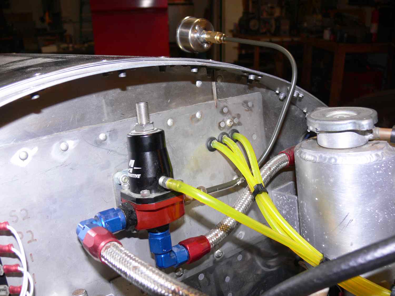
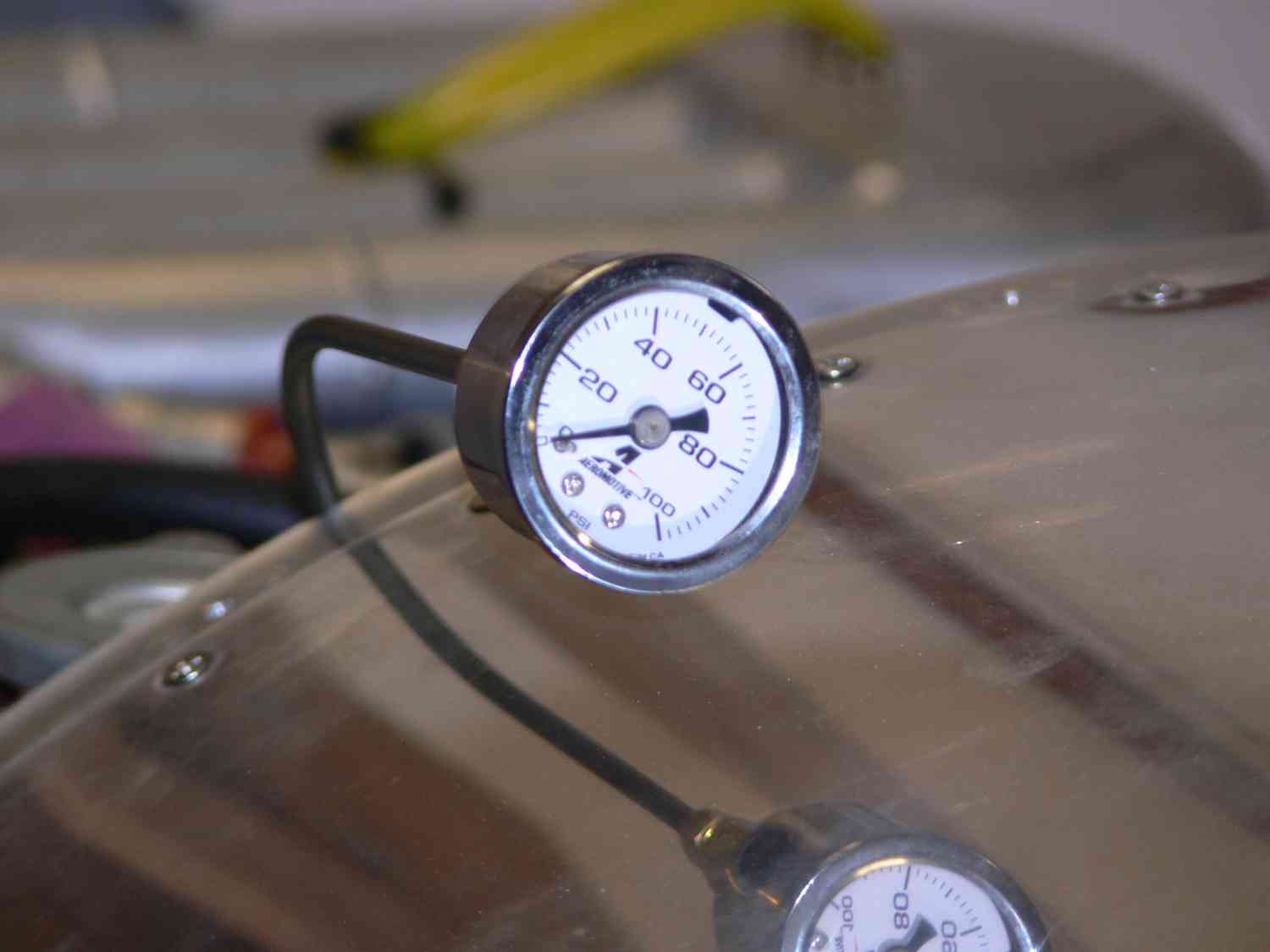
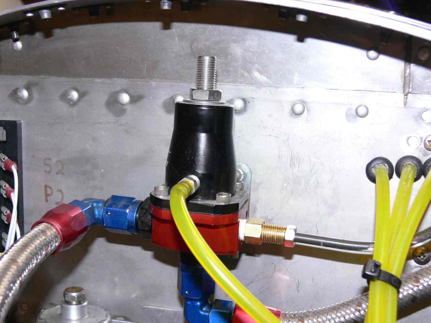
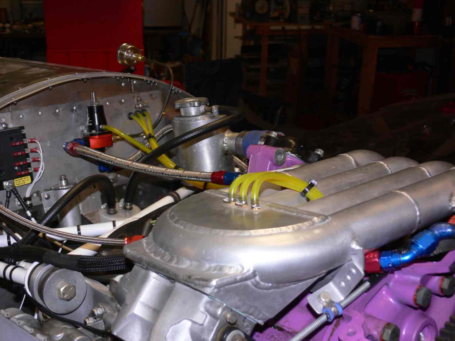
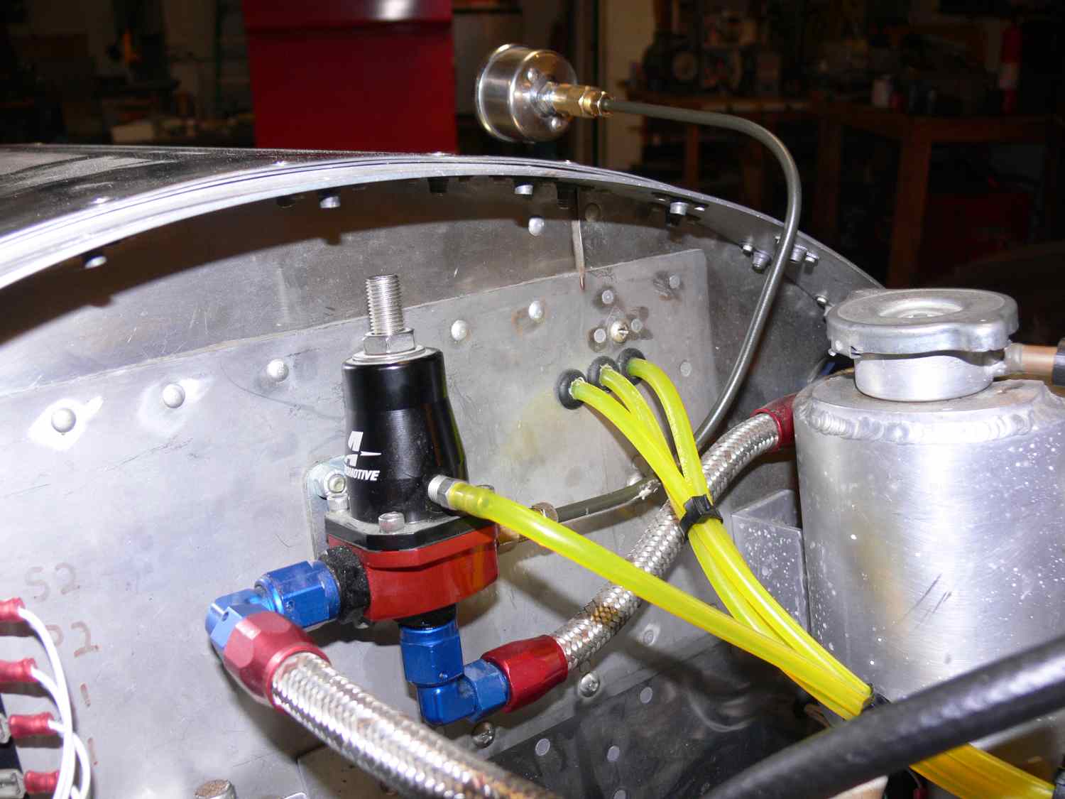
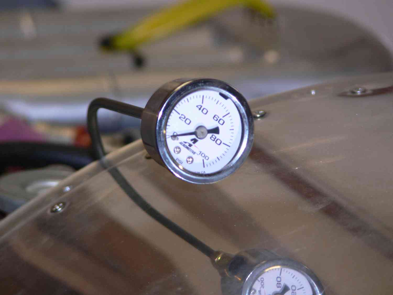
What brand of fuel pressure sensor are you using? Take a pic and
send it to me. This is the one I have in the RV4.
Paul Lamar
Fuel pressure to see & verify that the regulator is doing what we
expect. There have been a number of cases where people have purchased
the wrong fuel pressure regulator and then had trouble figuring out why
their engines wouldn't run as expected. It just seems like a good thing
to see, but if you have an EM-2, you already know that it is/isn't
working.
Mark
The fuel pressure sensors are expensive. If you have a spare you could
loan it to me. They apparently are a simple resistor so we will have
to measure the resistance and design a circuit that will change them
to a zero to five volts out circuit. That will mean pumping them up to
max
pressure of around 100 psi. Lacking that you could try measuring yours
with the engine running and an ohm meter. I am open to other ideas.
Paul Lamar
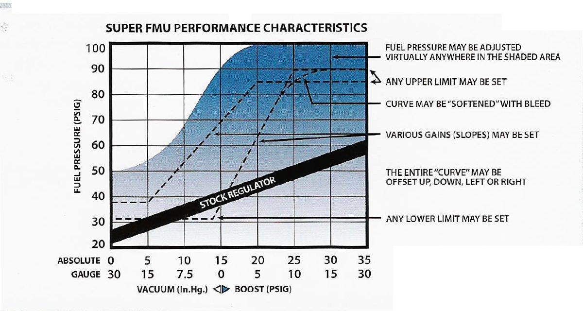
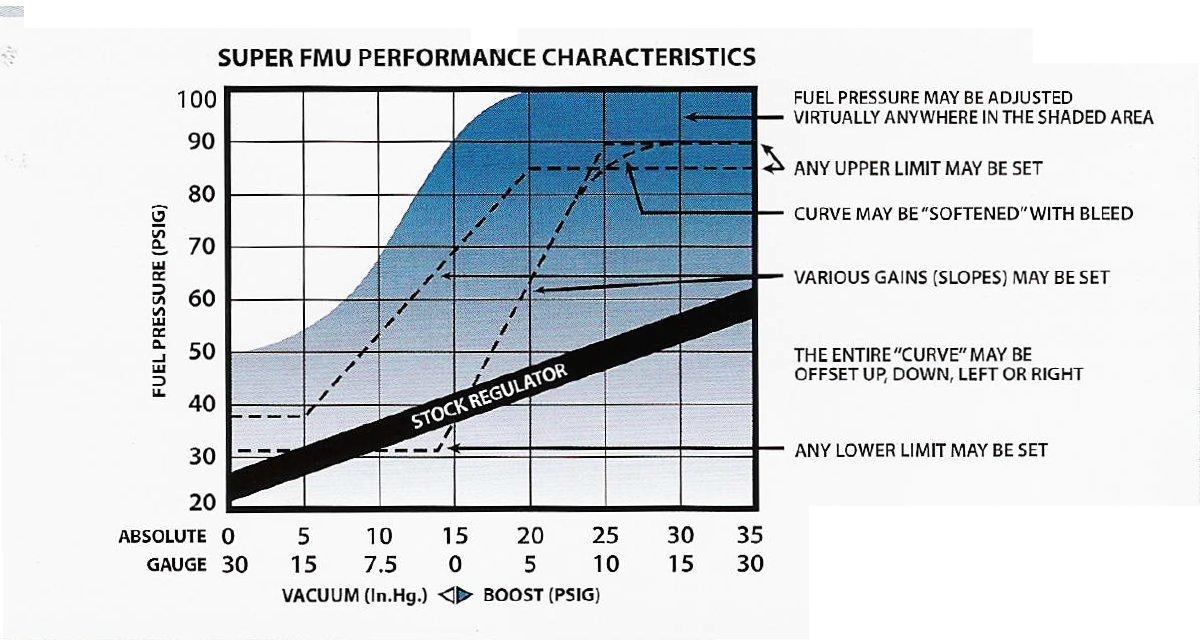
Fuel pressure is not constant for most automotive fuel injection
systems, it goes up and down with MAP. The DIFFERENCE between fuel
pressure and MAP is supposed to be constant in order for the quantity of
fuel delivered to be linear with injector pulse width.
To measure fuel pressure for setup/test/analysis, use a Freescale
MPX5111GP or MPX5100DP for low-pressure (up to 30PSI) or MPX5700GP for
higher pressures. Either for $15.74 from Newark. These are not made for
direct reading of liquid so tee them into the fuel system and keep them
above the highest point of the fuel system. Not for permanent
installation,of course.
Victor Roberts
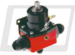
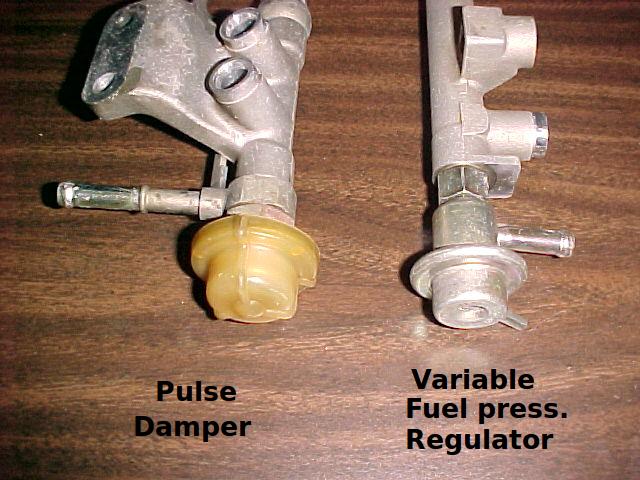
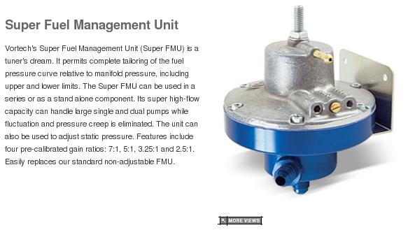
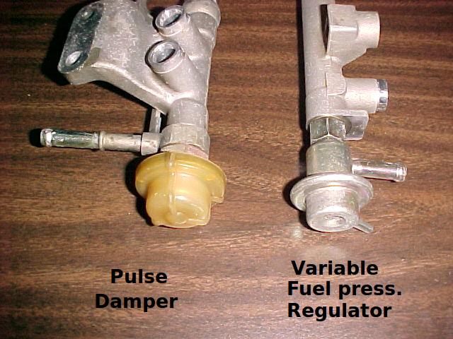
Good point Victor. Not all pressure regulators are connected to the
intake manifold. Tracy's computer can be tuned to deal with either
configuration.
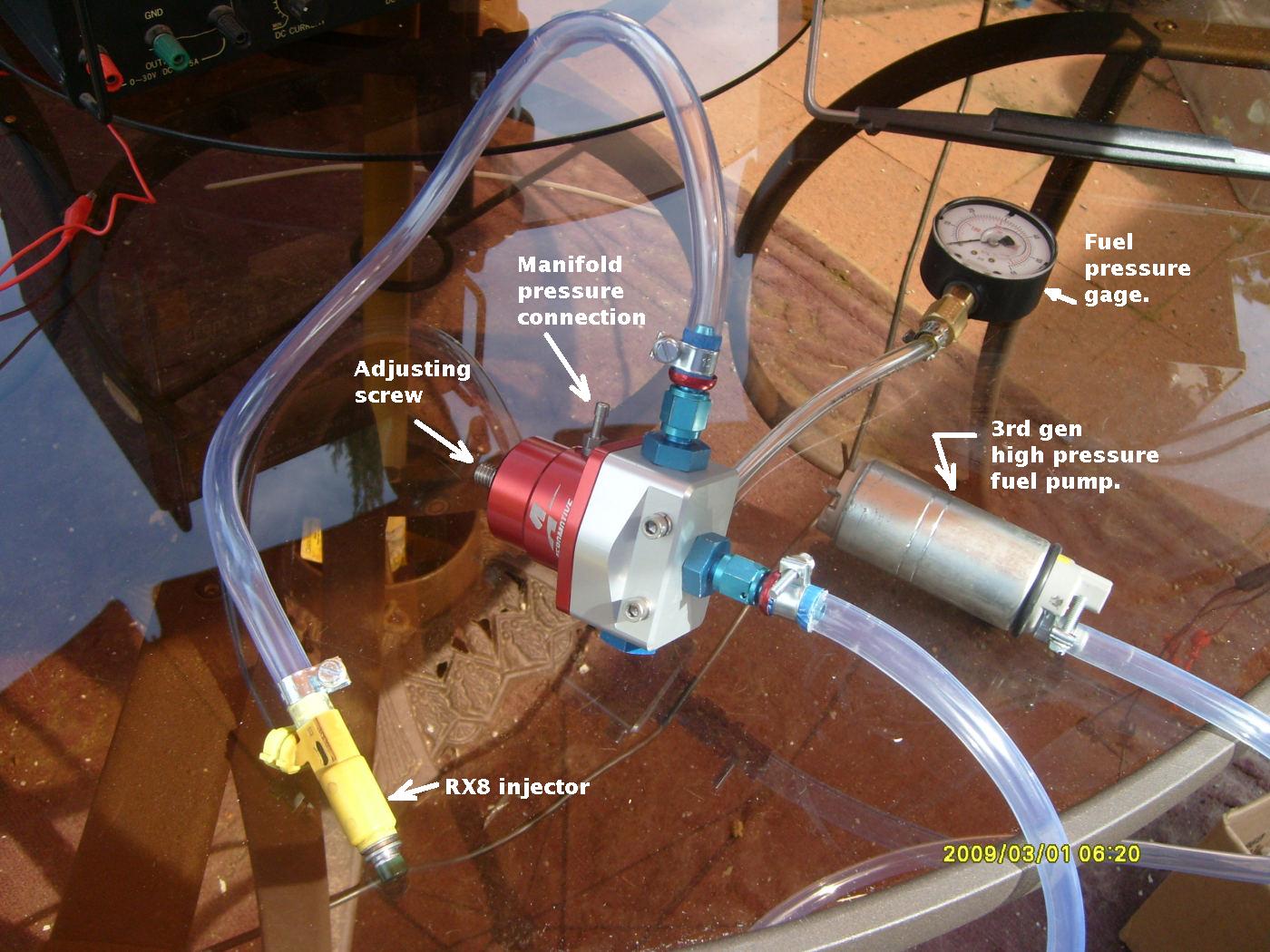
What connecting it to the intake manifold does, in effect, is widen the
dynamic range of the injectors. For turbo engines it is essential as the
pressure ranges in the intake manifold are much greater. What I have
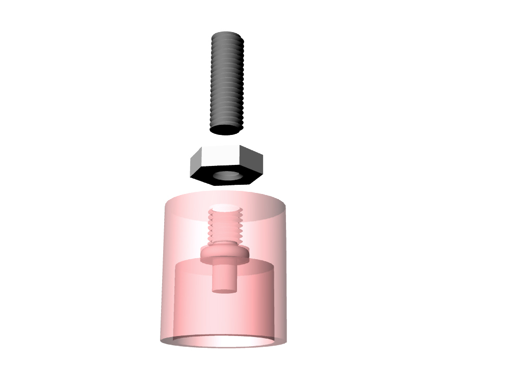
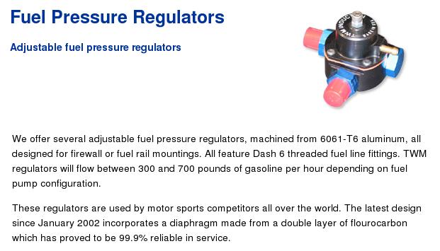
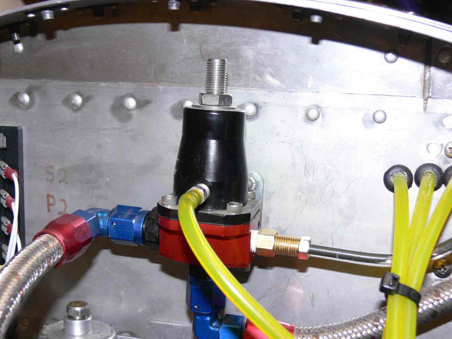
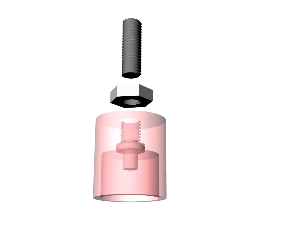
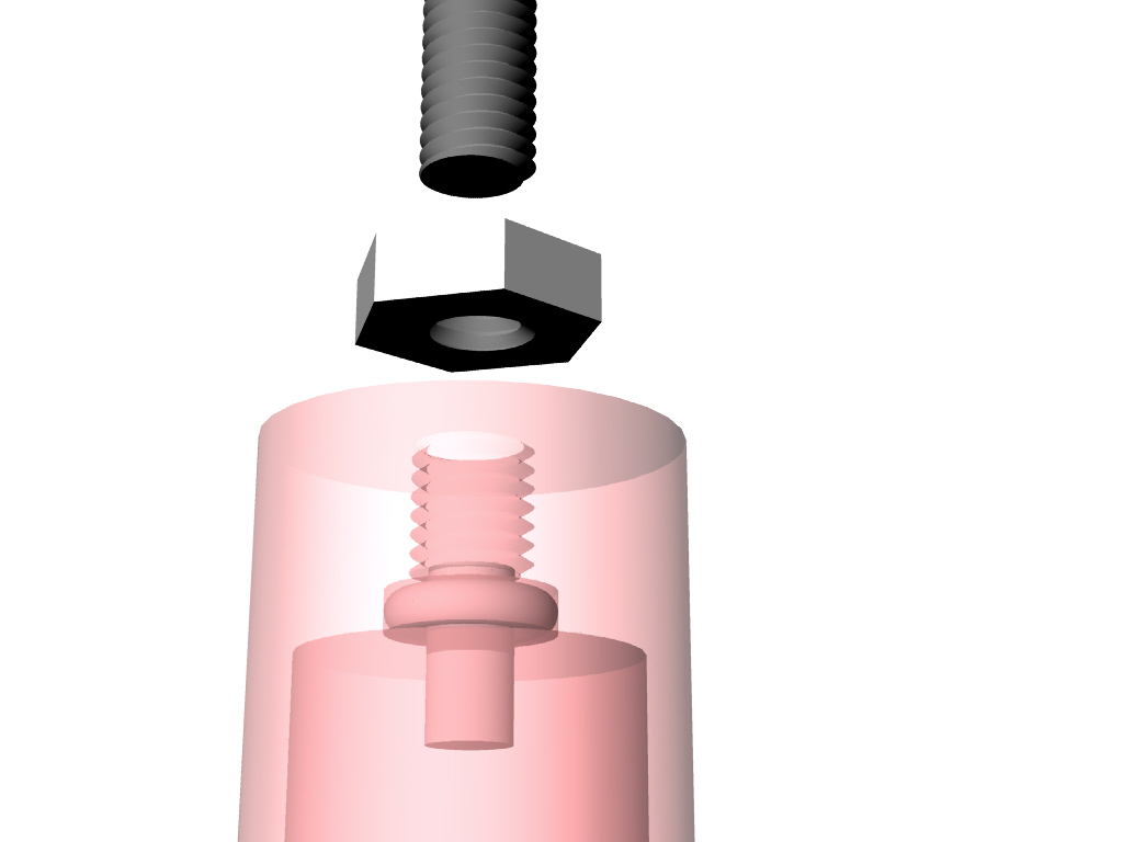
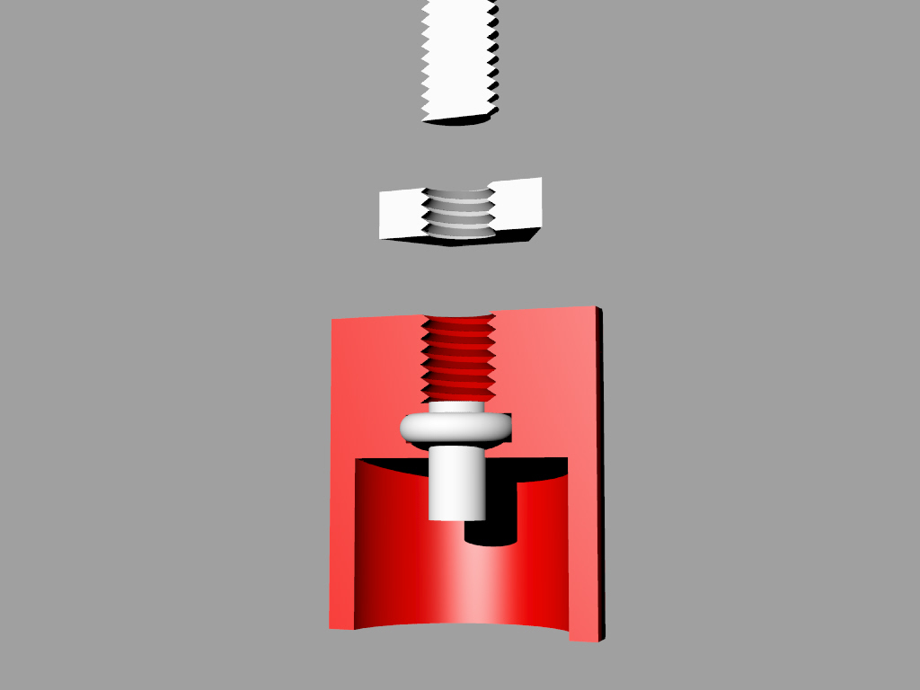
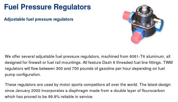
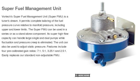
found is just about all adjustable fuel pressure regulators I have
tried so far leak vacuum more or less around the adjusting screw. At low
speeds they will work differently than they do at high speeds.
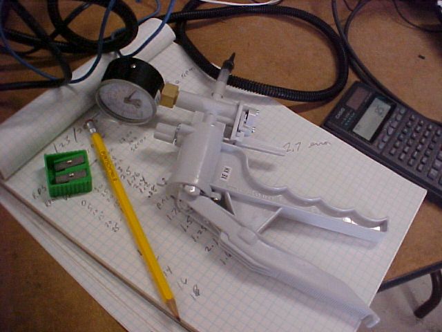
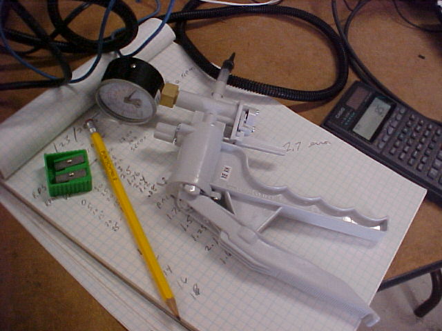
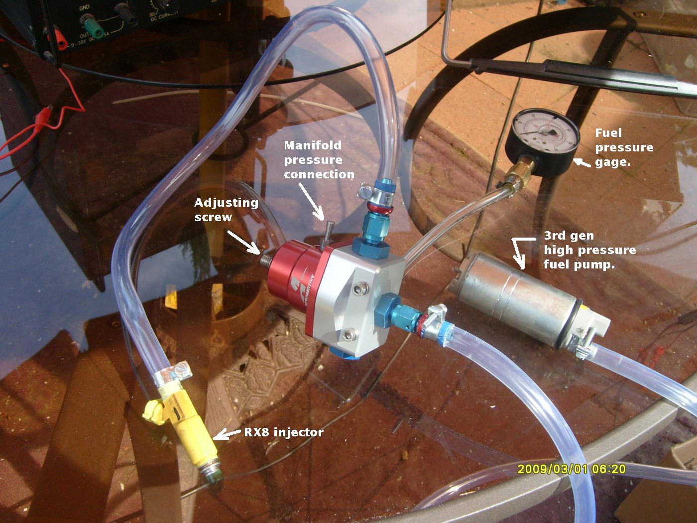
Here is how to test your pressure regulator. Get a hand vacuum pump at
your local auto parts store. Suck the air out of it and watch the vacuum
gage. The vacumm will more or less leak off slowly. I called
Aeroproducts on this and they said it is "normal". According to them it
had no real effect on operation.
The non adjustable stock fuel pressure regulators are to be preferred as
they cannot leak vacuum unless they fail outright.
As far as the FreeScale pressure sensors I have hesitated to use them
for fuel pressure as I did not think the plastic would withstand the
fuel. Perhaps I am wrong.
I noticed the fuel pressure in my RV4 is all over the ball park. I
suspect it is the fuel pressure sensor or where it is installed in the
system so I am in the process of using a mechanical pressure gage to
check it. Right now I think I have a wiring error in the EFI and the
engine is not running. Only so many hours in the day :)
Ed and I are also working on a new gearbox design.
I am also trying to get my hangar better organized.
Paul Lamar
--
The Rotary Engine News Letter. Powered by Linux.
ACRE NL web site.
http://www.rotaryeng.net
You Tube key word PaulLamar2
Copyright 1998-2012 All world wide rights reserved.