Paul,
I have a thought on a more advanced Engine Controller for the Rotary.
I would like the engine to be able to adjust automatically to changes
in operating conditions. In the current EC3 setup, MAP is used to
control the proper amount of fuel, and it takes a lot of calibration
before a conversion is done properly.
Now what if we can monitor a MAF sensor? If we know the air mass at
any given time, together with rpm and displacement, we can calculate
how much fuel to squirt into the engine. Since Air mass changes with
altitude, the engine can automatically reduce fuel consumption
accordingly.
To make programs simple, I propose a push button to fine tune the
leaning process. I assume that on the climb, we can let the engine run
a little rich, so we can settle for a simple loop similar to an open
loop mode in the cars, but once we are at our cruising altitude, we
can push a button, and my monitoring CHT and EGT, we can program the
EC to do an automatic cycle to find the best lean point.
On descend, we can either automatically take the best lean mode out
and get into open loop mode by monitoring the MAF, (Air becomes dense,
while rpm is constant and volume of air is constant). Alternatively,
we can add one more button to manually get into open loop mode.
Henry Nee
Sounds great Henry. What are you going to write it in?
I would like to see ASM as there is a one to one between what you tell
it to
do and what it does. Also you can control time down to the nano second.
Perhaps you have someone over there that can do it in ASM
and comment it in English. I can help with the cost up to a few
hundred. If
it is done in high level language perhaps the comments can be correlated
with the ASM listing.
BTW are you back in China? Ed wants to buy some ceramic bearings for
our new
PSRU's
We have your Chinese address unless it got lost in the last computer
glitch.
I am now using Ubun 10.04 and I like it better than Fedora 7 but there is
still room for improvement. It keeps bugging me on the bug fixes.
Shall I do
it? I have the second hard disk working so I will back up everything
first.
Paul Lamar
I am still here stateside. I am scheduled to return by the end of this
month. I think everyone in China is off due to Chinese New Year so no
point in trying to buy anything until end of this month.
IMHO, Some Assembly, and some higher level language. I like Pascal,
but C may be easier to write. I don't know if Basic has the
performance to do floating point math efficiently. I think we need a
Basic Compiler so we can pre-compile the code then it should run much
faster. I like a lot of timing margins so that there is enough CPU
cycles to deal with unforeseen event combinations.
I am not sure what language it is going to be, but I am sure assembly
will be part of it so thank you for your offer to help. I might
actually need you to try this out on your engine first as I have
nothing to test it yet.
I am hoping to do this with a ladder diagram. Ladder diagram is used
widely in control systems because it makes it easy to isolate feedback
signals from contaminating the inputs.
Let's assume that we can run to 12,000 rpm on a rotary (For those
needed extra horse power and have the money to use light weight
rotors), that will be 200 turns per second, or 5 ms per turn. I think
I can handle all the calculations in that time. The problem is that I
may not have enough time if I have to squirt to each rotar. If I
remember correctly, I will have to squirt into one chamber per turn
per rotor, so in a two rotor system, I have 2.5ms to get the job done.
Also, I think it is necessary to have a real time system so squirt and
ignition timing needs to be more precise. My feeling is to use a
second processor dedicated to do just that, and it will get the squirt
duration, and ignition time values from the first processor running
ladder diagram software. Of course the second processor will be in a
simple loop and can be as simple as the basic program you have
suggested in the past, Or we can write it in assembly and be even more
precise.
The idea of using two separate processor is to have an isolation
between the real time processing done by the second processor, and the
"not so real time" processing done by the first processor. In "not so
real time" I mean it is not going to hurt us if we miss one cycle and
use an old value instead of a new one on fuel and ignition as engine
may not have changed that much in speed over 2.5ms, therefore timing
is still OK. And this is only a potential problem during initial
spooling up of engine speed.
Once we separate the tasks into two processors, we eliminate one major
concern I have with processors, that is multiple events happening at
the same time, and the resulting lack of processor power means that
calculated data can feed back into the input and causes unforeseen
conditions! So separating the job to two separate processors has the
advantage of a more reliable software system than doing it all in one
unit.
I would also like to add two backup processors, one on the main loop,
and one on actual squirting and ignition timing control, and have a
manual switch to switch control from one to the other when needed.
Between the processors, I would use a I2C bus to pass the output of
the ladder diagram to the second processor. I think it is easier to
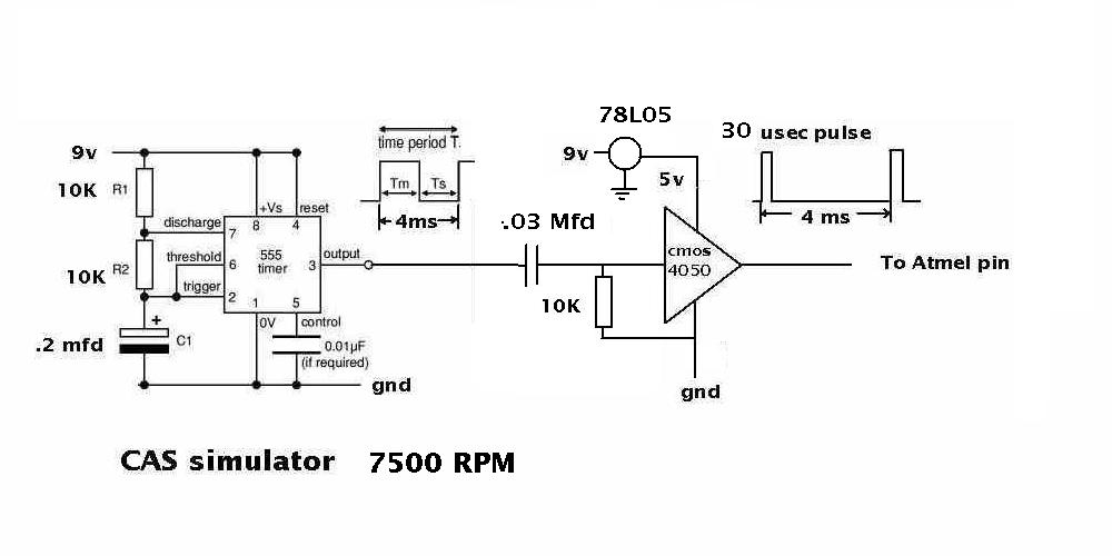
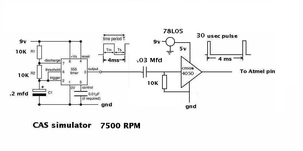
interface this way than to use a low cost 555 with this approach.
Henry Nee
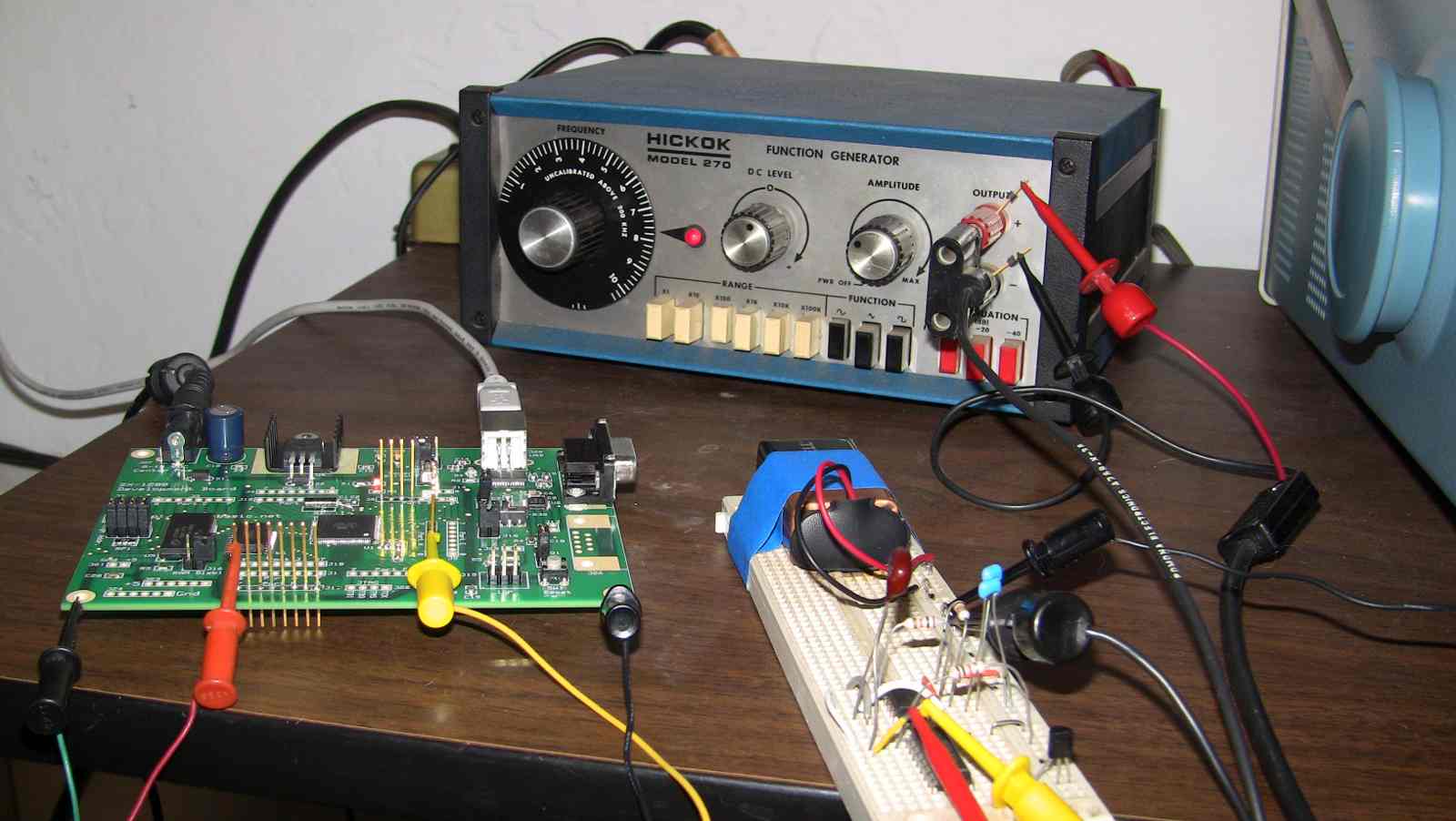
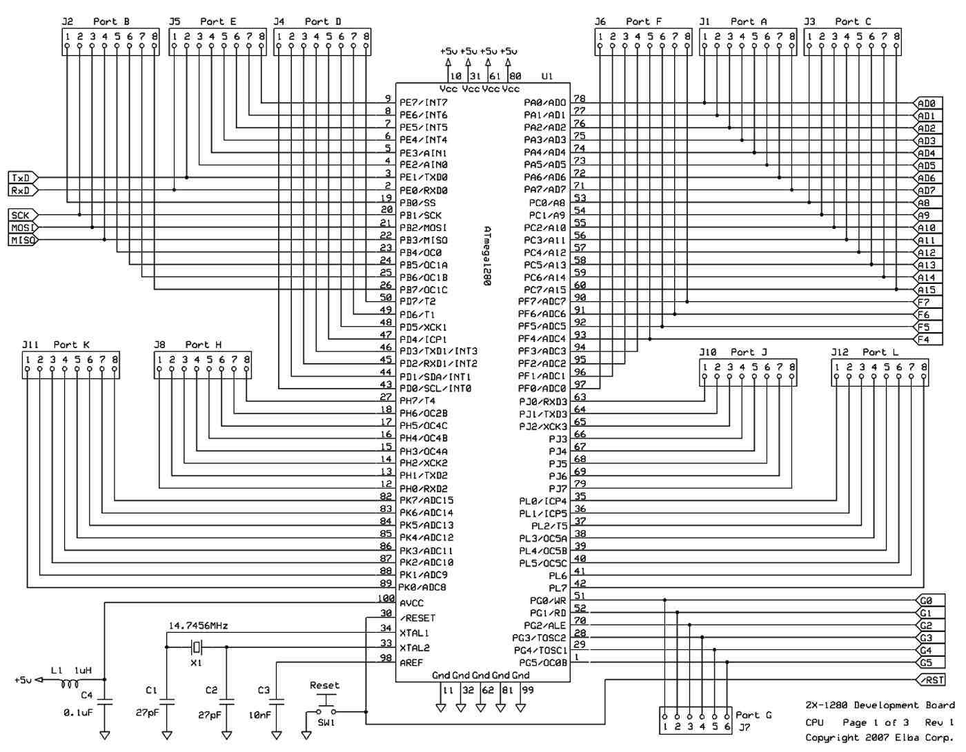
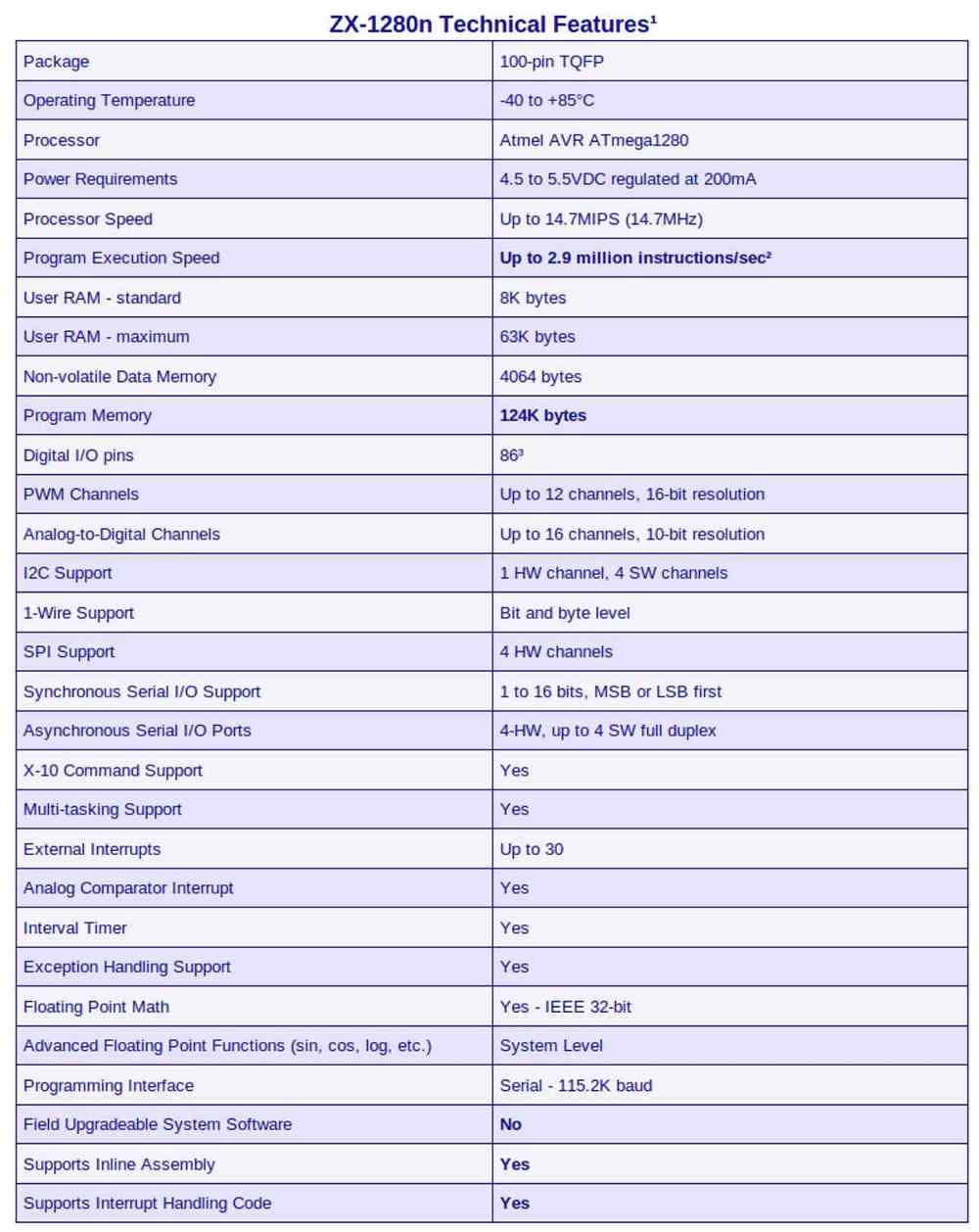
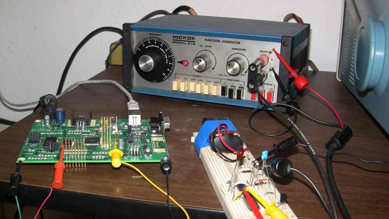
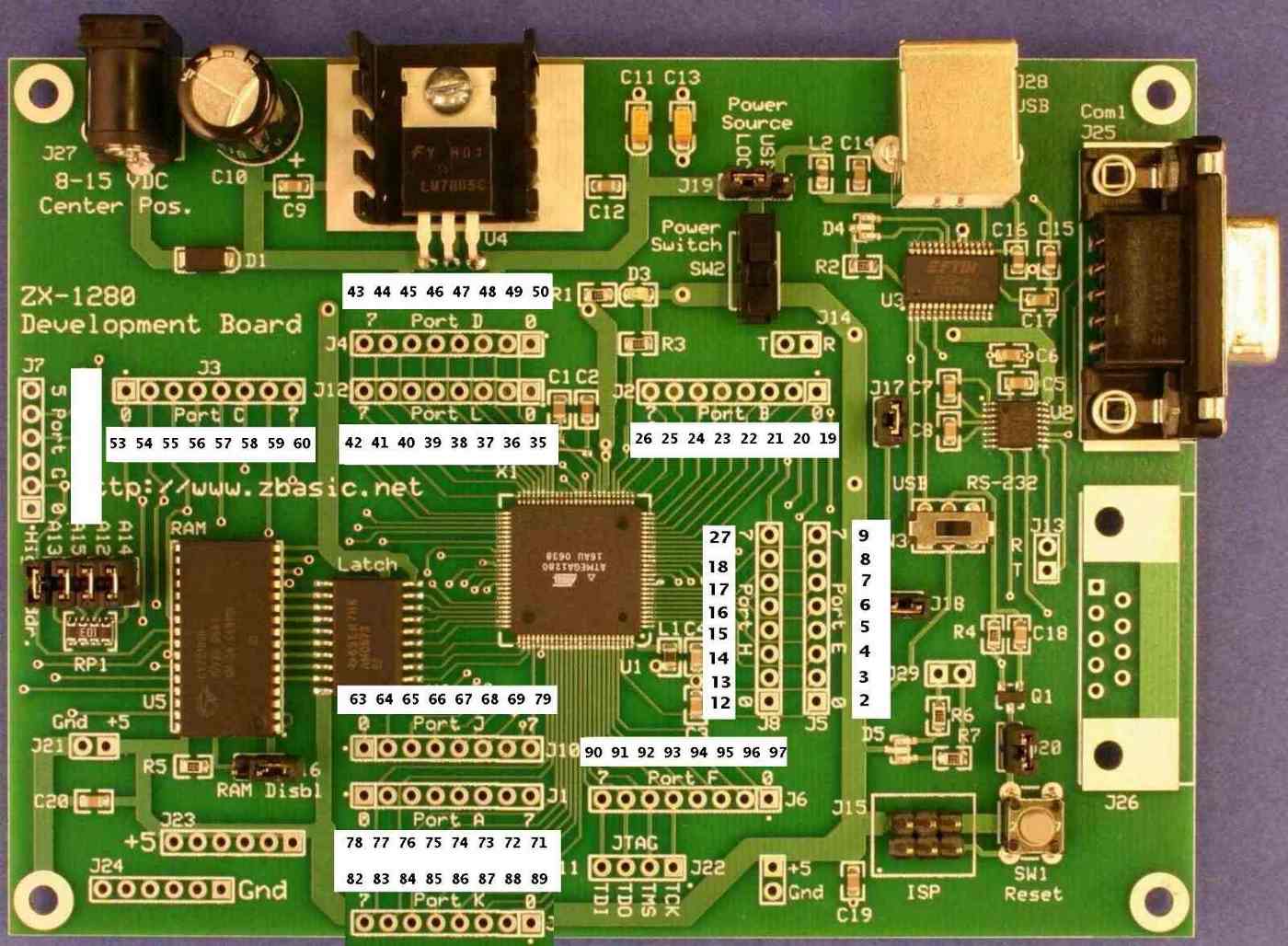
Henry, take a look at ZBasic.
It is fast, very easy to learn and compiled.
http://www.zbasic.net/
I have done a lot of work with it and it is very readable
and easy to start using.
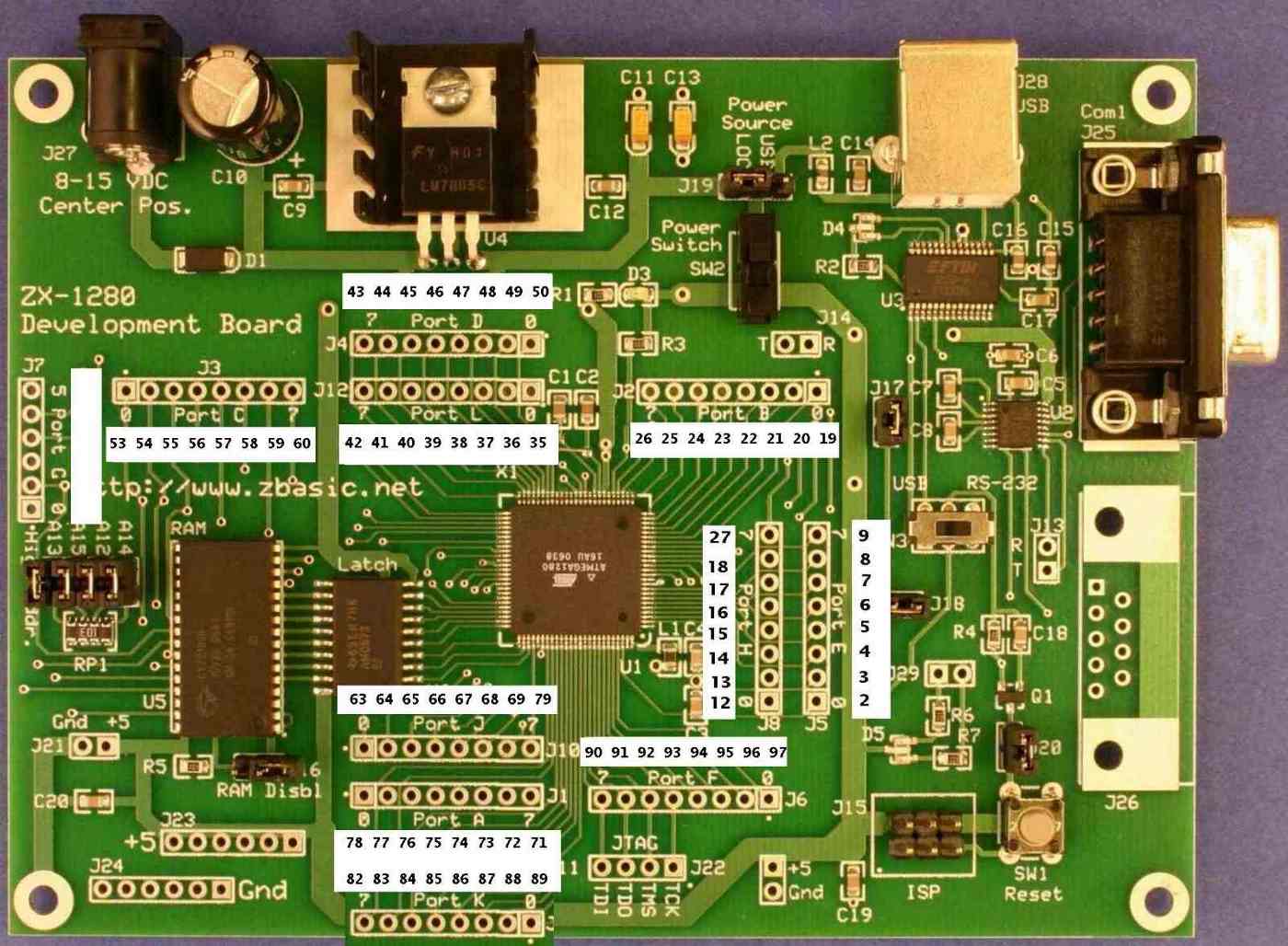
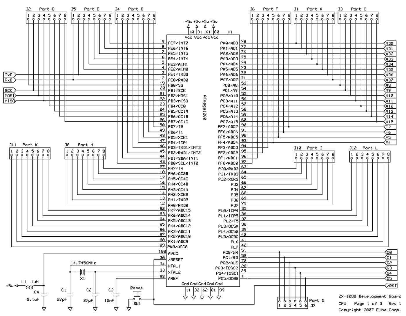
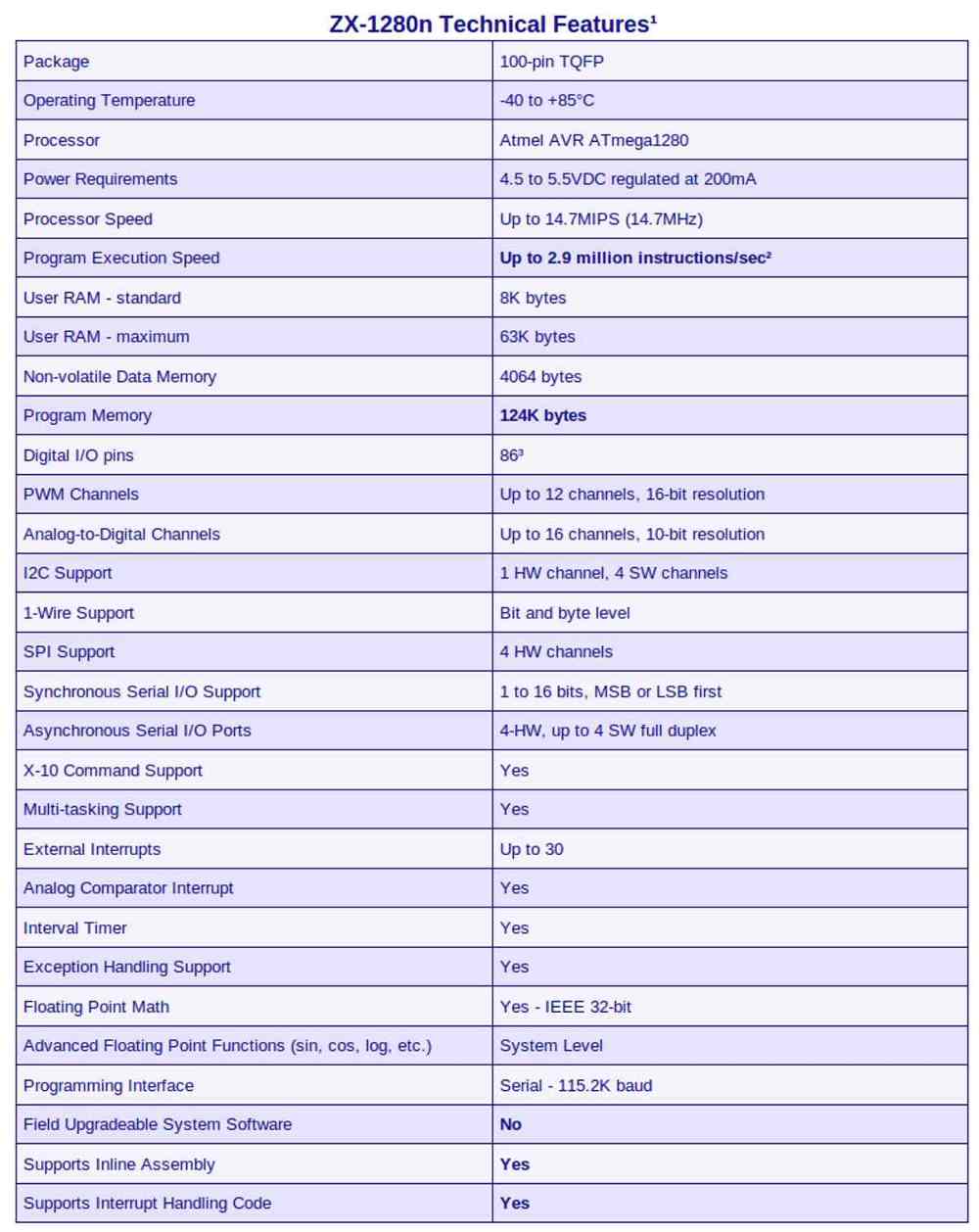
The $100 board is a bit over kill I/O wise but hey it is cheap enough.
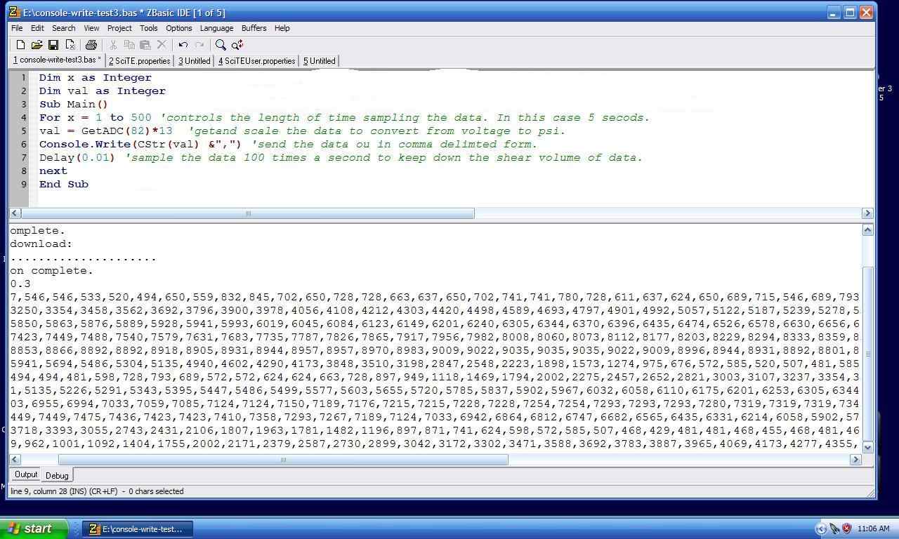
Crude out line stub EFI for CD ignition and injection.
------------------------------------------------------------
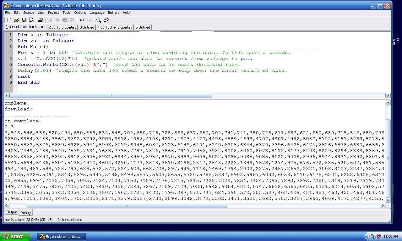
Sub Main()
Call PutPin(12, zxOutputLow) ' pin 12 CAS 1 will be at logic zero
Call PutPin(13, zxOutputLow) ' pin 13 CAS 2 will be at logic zero
dim x as long
'check and wait for CAS
'do
for x = 0 to 3000000 'develop only
If (GetPin(12)=1) then
Call rotor1
end if
if (GetPin(13) = 1) then
Call rotor2
end if
'loop
next x 'develop only
end sub 'main
sub rotor1() 'it is 22 degrees BTDC
Call PutPin(14, zxOutputHigh) ' trigger ign rotor1
dim add1 as integer
dim add2 as single
dim add3 as single
add1 = GetADC(82) 'MAP sensor val must be an integer
add2 = CSng(add1)
add3 = add2/10.23
'injection
' prepare for 100Hz Fast PWM using channel 2
Call OpenPWM(3, 250.0, zxFastPWM)
Call PWM(3, add3) ' generate PWM with
Debug.Print " = " & CStr(add3);
Call PutPin(14, zxOutputLow) ' turn off ign trigger
end sub 'rotor1
sub rotor2() 'it is 158 degrees ATDC
'Debug.Print "rotor 2"
End Sub 'rotor2
----------------------------------------------
Paul Lamar
--
The Rotary Engine News Letter. Powered by Linux.
ACRE NL web site.
http://www.rotaryeng.net
You Tube key word PaulLamar2
Copyright 1998-2012 All world wide rights reserved.