Paul,
I made a major breakthrough today. In preparation for hooking up the
Hytek data logger, I decided that it would be good to install check
valves on each vacuum line leading from each rotor housing. (For
those
who are unaware, I am running a peripheral port 3-rotor with a PL
slide
throttle.) My system measures MAP from the unused oil injection
ports in each rotor housing.) Not sure what possessed me to do a
ground run right then, but I ran the engine right after installing
the check valves. Now keep in mind that typical MAP readings at
idle up to this point was approx. 17" Hg. Well, today MAP readings
were in the 14.4" -
15.0" Hg range.
Then it dawned on me that the way the vacuum lines were
plumbed the RWS EC-2 would see an average of all three rotors.
Since each rotor is 120* (crank degrees) apart in their 4-stroke
cycle, the MAP would be quite a bit different for each rotor. By
installing check valves in the vacuum lines, I have isolated each
rotor from the other two and I am measuring the lowest vacuum. Idle
is now down around 1500 rpm, but the mixture is way lean, so it
appears that a re-tune is in order. I'll probably re-set the RWS EC-
2 to the factory defaults and start the process over from the very
beginning.
We need to stress to anyone that is measuring MAP in the rotor
housings to install check valves in each of the lines.
Mark
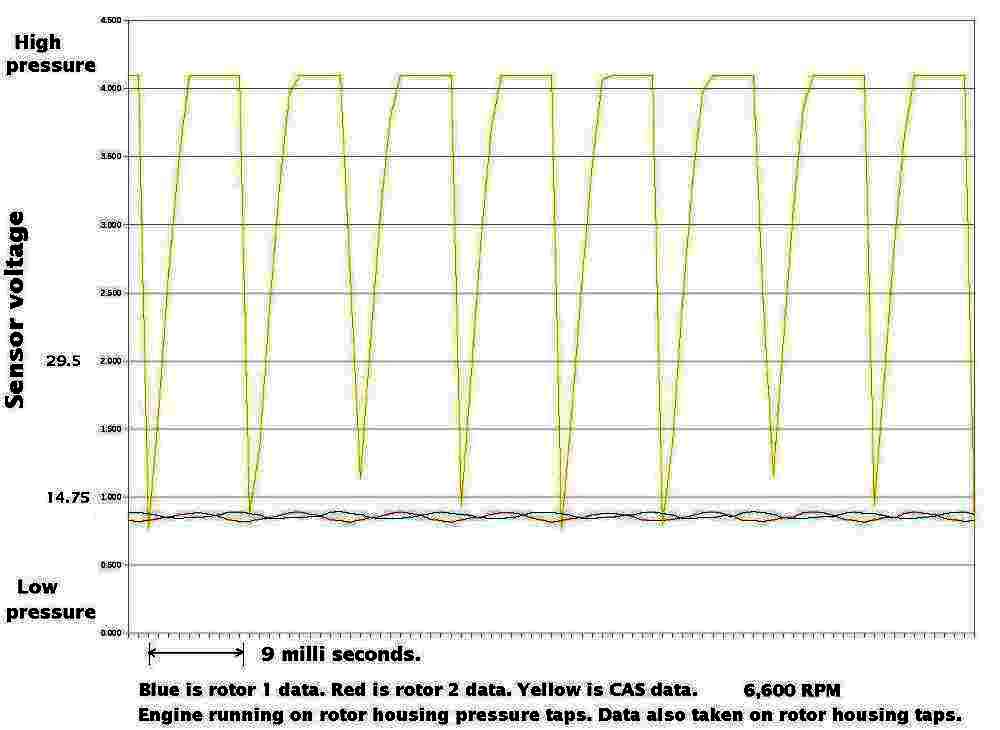
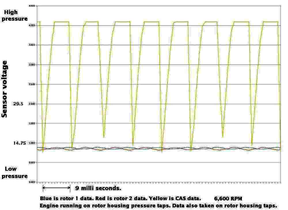
Good work Mark. Here is the latest voltage to pressure chart.
Paul Lamar
Mark,
To me check valves tells me you allow "flow" one way and block the
other. If
that is the case you either inhibit sense or trap it. Also, is there
a crack
pressure for these check valves? Crack pressure is the pressure to
get it to open.
Dale Davies
Dale,
You have put your finger on the same issue that Tracy Crook pointed out.
If there is no way for the MAP to rise, then the engine may have a
stumble when accelerating. I did not experience that during my brief
ground run, but will be looking for that on the next run. (It is
possible that the check valves I am using don't seal very well and are
allowing a controlled leak.) I may have to re-think this, but it sure
opened my eyes to a problem I hadn't realized that existed until
yesterday. I may have to try using only one rotor's vacuum for the
EC-2, and/or a small vacuum chamber. I'm open for ideas here.
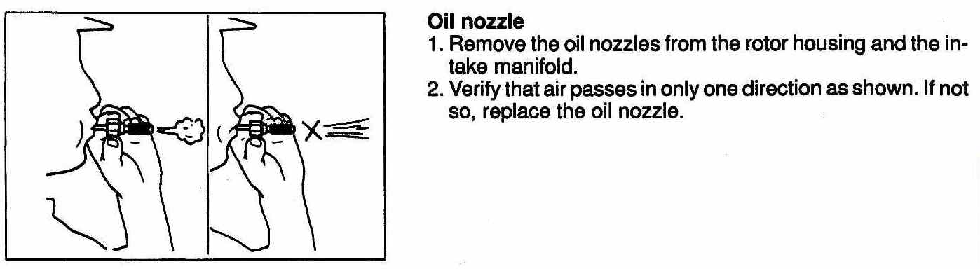
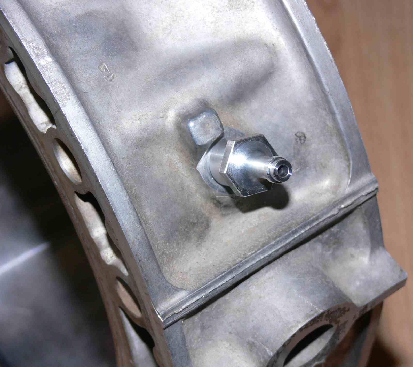
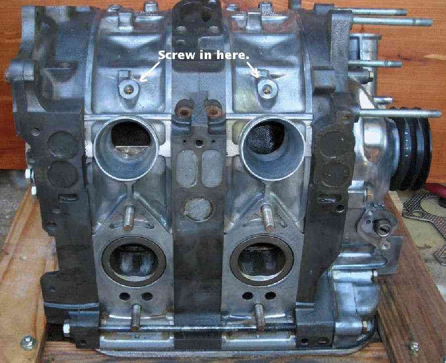
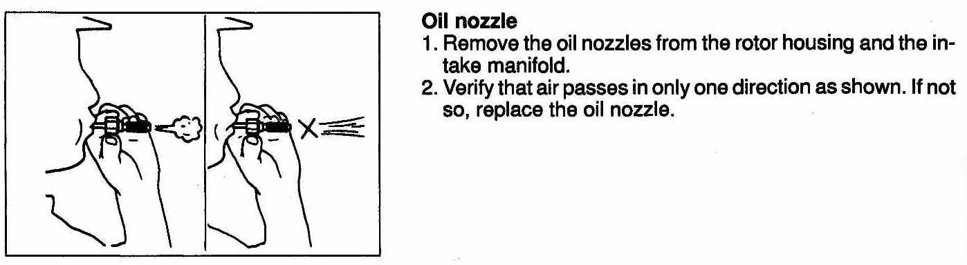
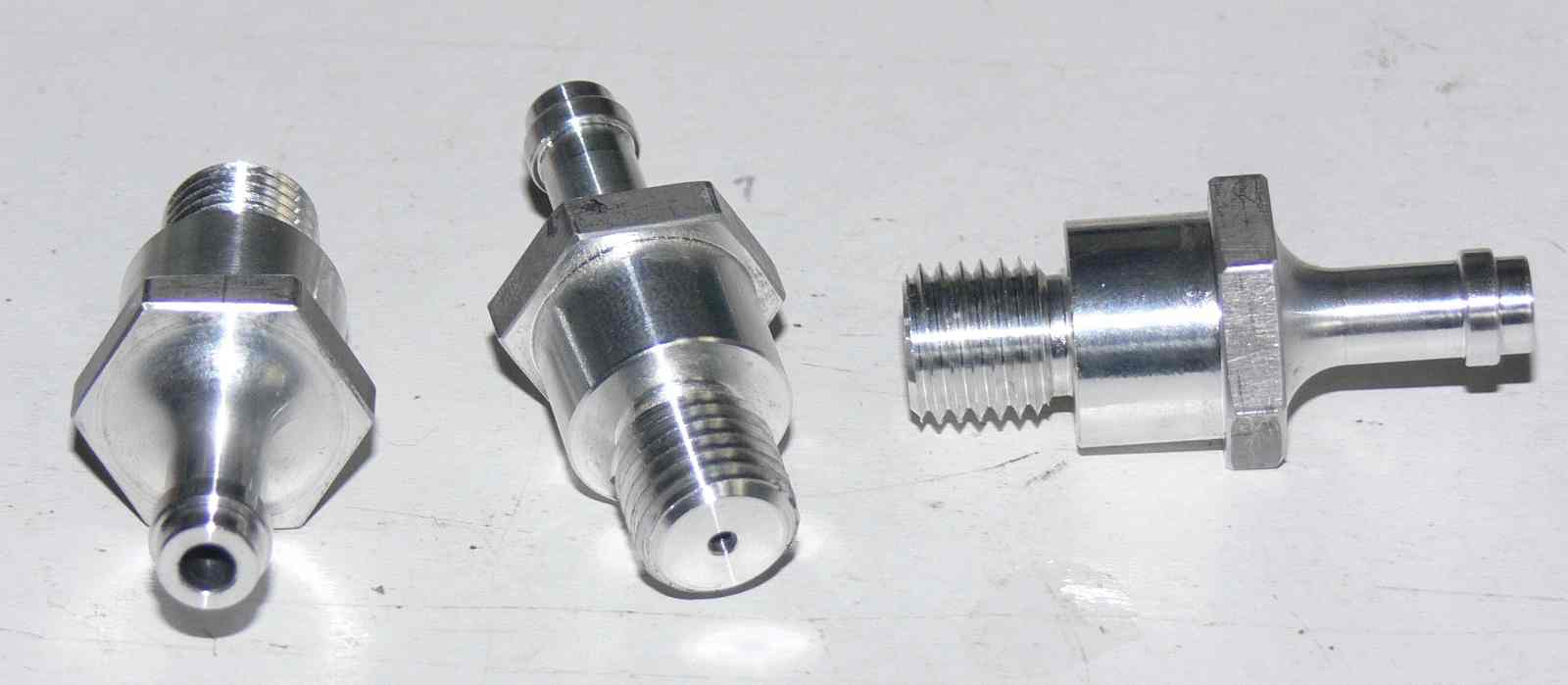
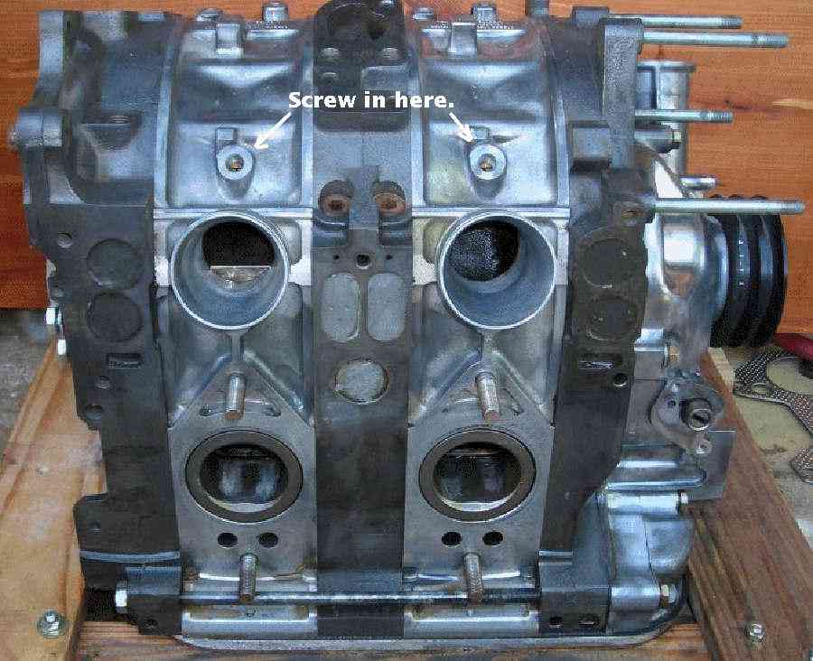
By the way, those little bolt-looking things that screw into the oil
injection ports are actually check valves. Anyone know what they are
used for in street applications?
Mark S.
Those those little bolt-looking things are custom made for Mazda. I
would not use them for monitoring intake manifold pressure.
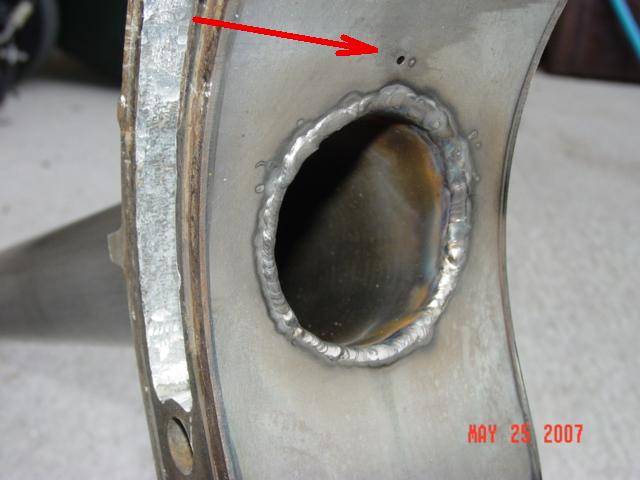
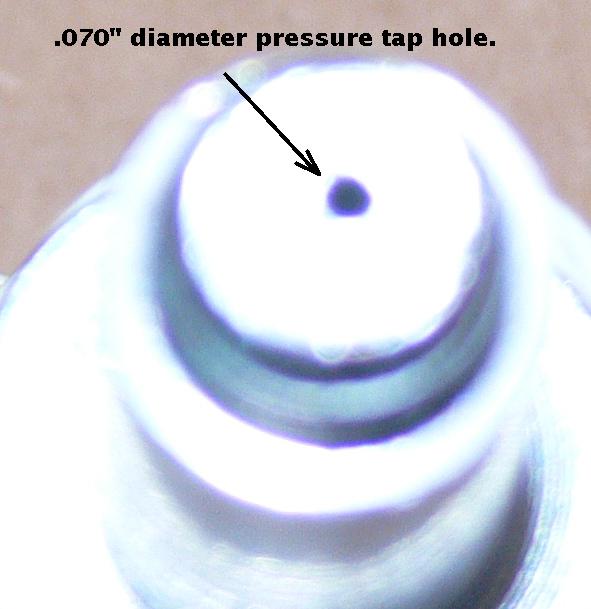
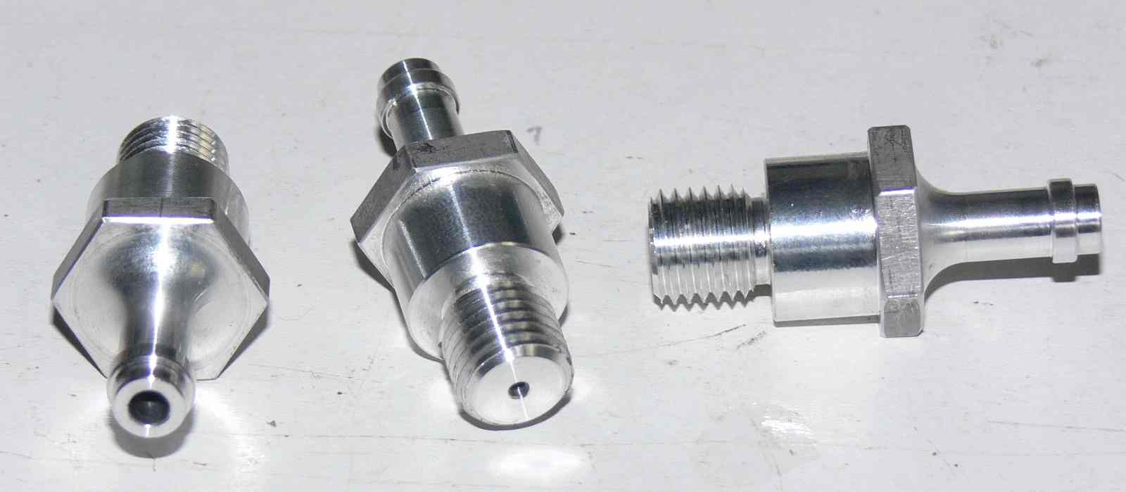
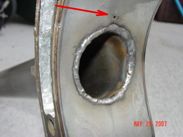
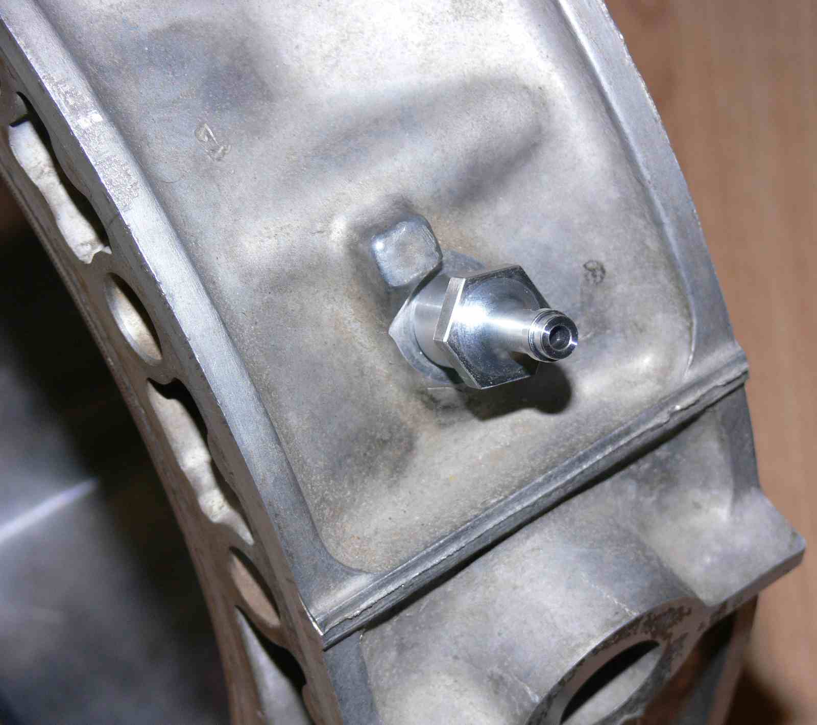
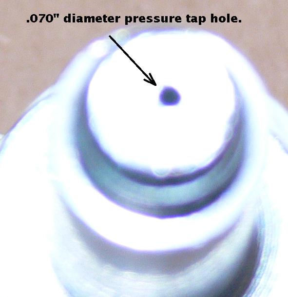
I have some pressure taps for that purpose that are custom made by NC
lathe. $20 each free shipping in the US. They have a small hole for
damping purposes. I think you will need to T all of them together as
Tracy uses only one pressure sensor to set the mixture for all rotors.
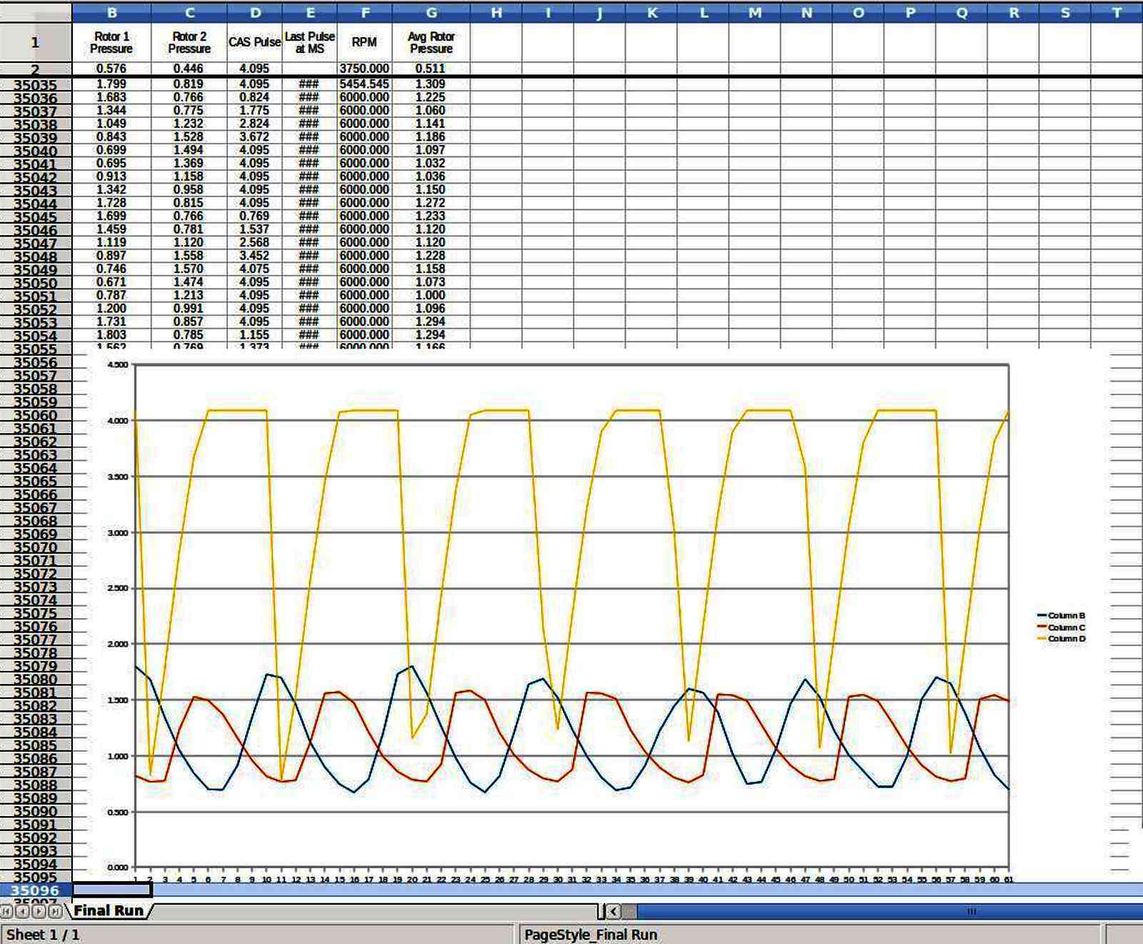
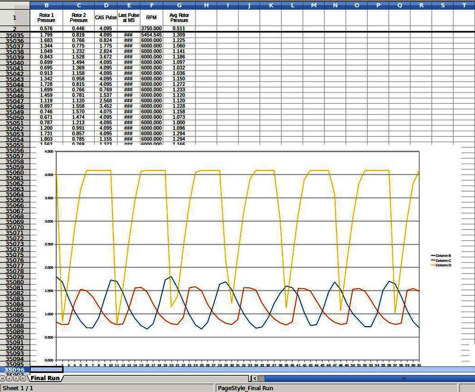
Here are some data on the old manifold pressure taps downstream from the
slide throttle and some data from the oil injection hole data.
The small hole in the NC made tap smooths the data greatly and averages
it as you can see.
In your case I would like to see the data from each rotor before it went
into a T directly from a pressure tap down stream from the slide
throttle but I don't think you have pressure taps installed there right
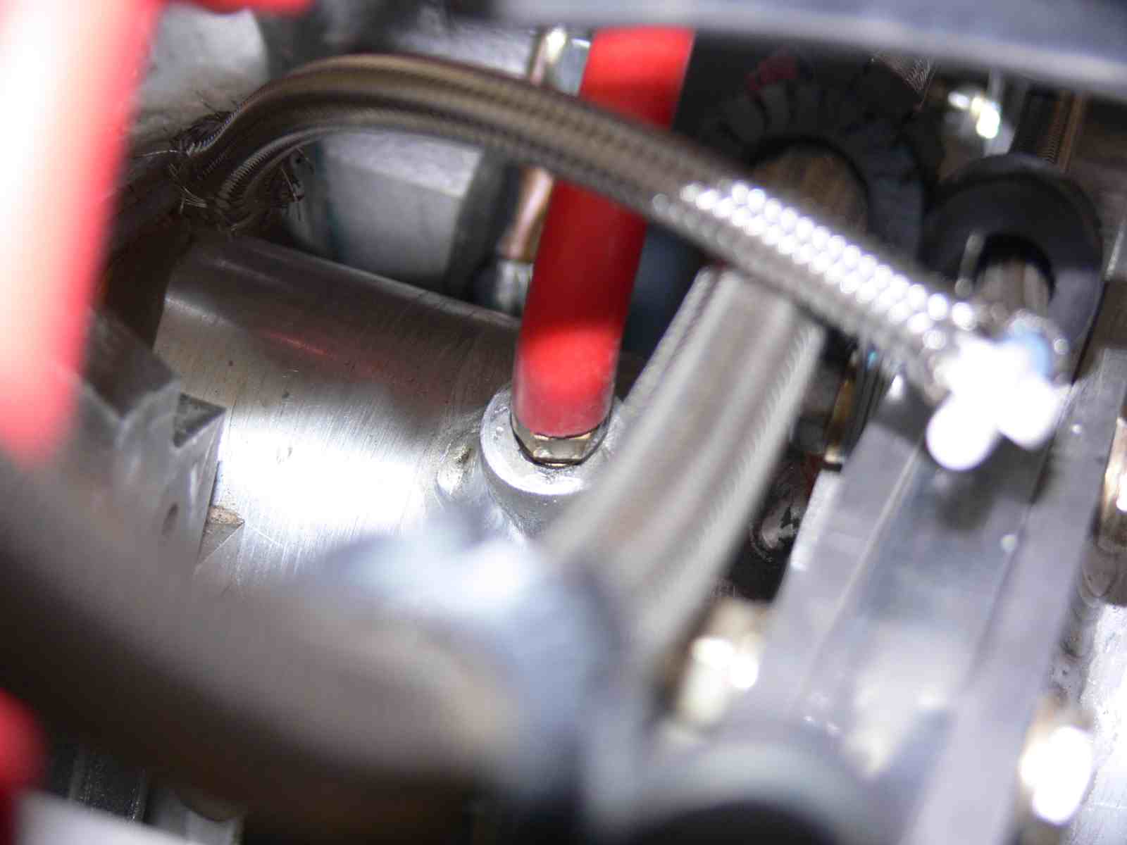
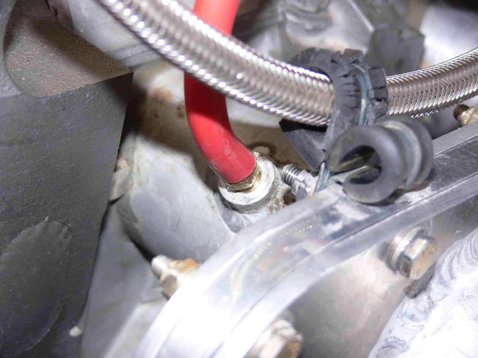
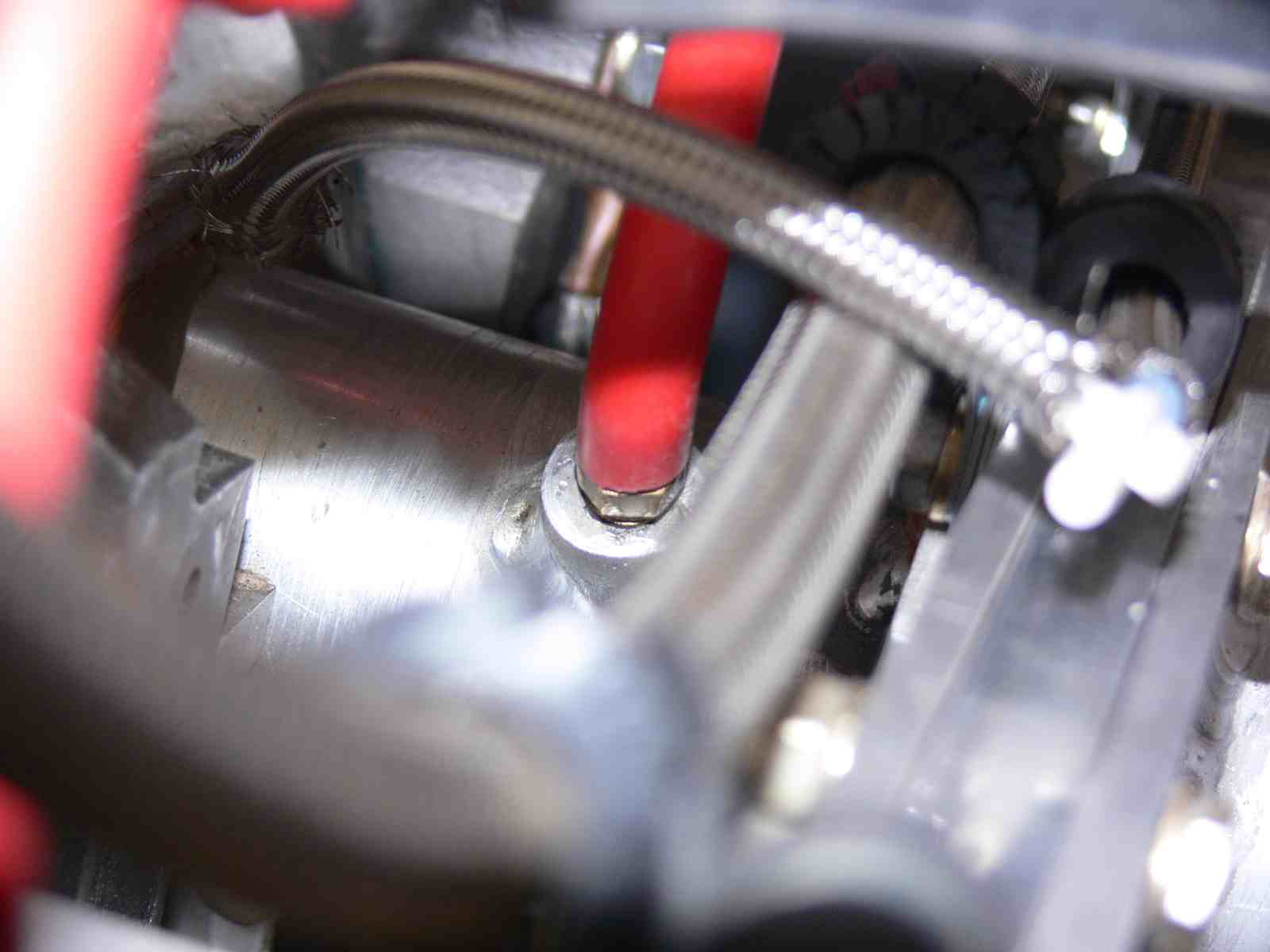
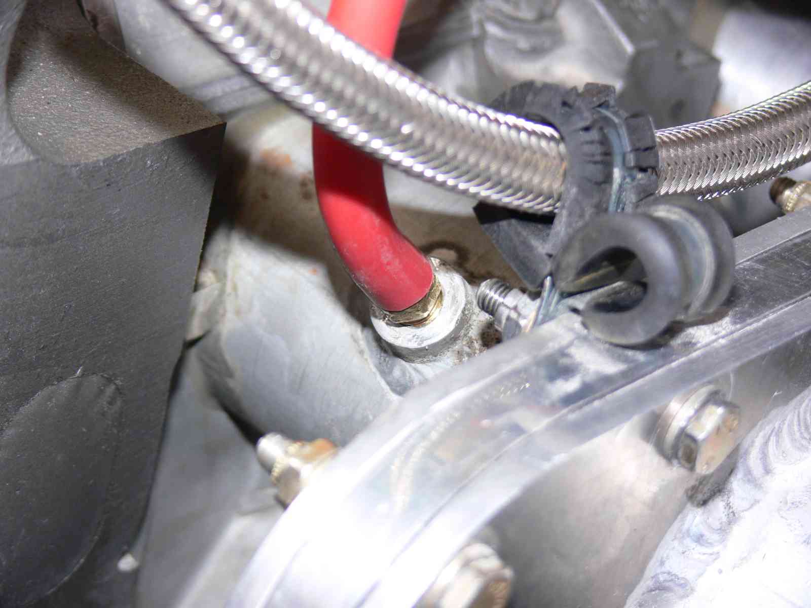
at the moment. See the pictures of Mark Suspinski's installation.
I would also like to see the data very close to the open part of the
slide during idle. That will take some tiny tubing welded into or JP
Weld bonded to the back slide cover near the opening just beyond the Teflon.
Since the wave is very strong Tracy's reading voltage number is going to
depend on when he takes the sample relative to the e-shaft position. So
far we don't know that but it can be found out when you connect the
injector voltage and CAS to the HyTek with an opto isolator. The
computer only takes microseconds to completely read the sensor sample.
The time of the peaks and valleys changes with RPM so the wave must be
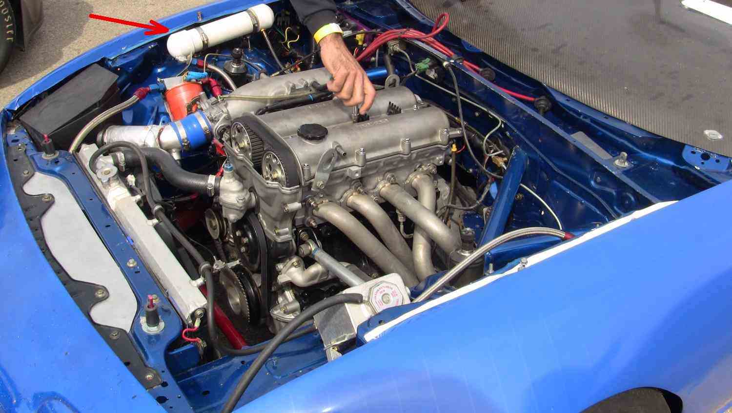
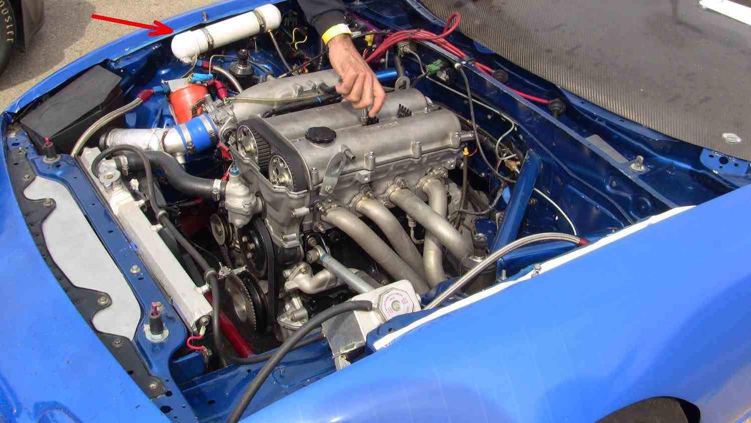
damped out some how. The car racers use a large section of PVC pipe for
this purpose.
Paul Lamar
--
The Rotary Engine News Letter. Powered by Linux.
ACRE NL web site.
http://www.rotaryeng.net
You Tube key word PaulLamar2
Copyright 1998-2012 All world wide rights reserved.