Paul,
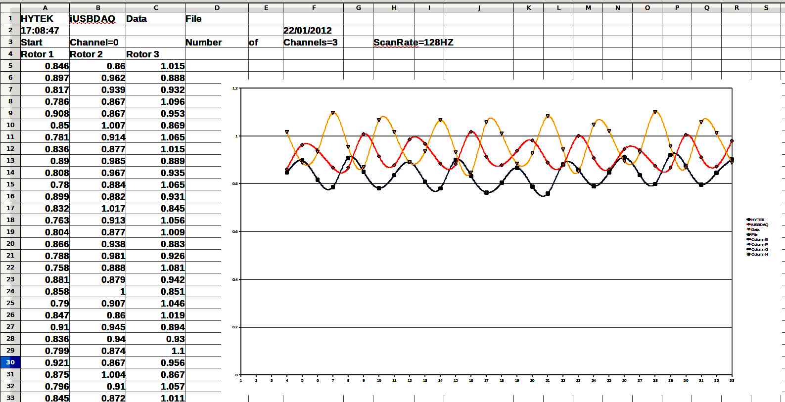
Attached is a copy of my first real data log taken today. One pressure
sensor per rotor, no trigger though. I revved it a couple of times
which you should be able to spot by the closer sine waves. Bottom line
is it confirms a serious mismatch in airflows.
Mark
The plenum is too small. One rotor is getting all the air.
Go back to your original plenum. I think you will notice an
increase in engine smoothness.
You need to up the sample rate to 1000 samples per second and limit
the time it is on to 30 seconds or less. That is more than enough
data to tell you what is going one. The curves will be more like
sin waves and smoother.
The three audio waves in the intake manifolds are 120 degrees out
of phase. That won't become real clear until you up the sample rate
to 1000 samples per second or higher.
If you put a five volt zener diode on the CAS signal you can feed
that into one of the analog channels. It does not matter which one
but AI3 would be fine.
Paul Lamar
Also,
I might suspect a low level grounding issue with the input to the DAQ..
Can you AC couple the inputs (a setting)?
Matt-
Basically they are DC signals. Converting to AC and then back to DC
would be impractical. I don't think there is a grounding problem as the
sensors are at or on the computer. Hoses run from the pressure taps
to the computer.
Paul Lamar
With a low sample rate and using the spread sheet chart to smooth the
curves the wave phase relationships are distorted. They should be 120
degrees apart.
Does anybody know how to increase the text size in open office spread
sheet charts. It is hard to read these titles.
Paul Lamar
--
The Rotary Engine News Letter. Powered by Linux.
ACRE NL web site.
http://www.rotaryeng.net
You Tube key word PaulLamar2
Copyright 1998-2012 All world wide rights reserved.