It's spring planting time in Wisconsin, and I my Briggs & Stratton
powered rototiller lost all spark.  I had to spring for what amounts to
a "new magneto".

Why wouldn't something like this work on a rotary/Wankel engine?
Two screws and a wire for the kill-switch is all that is required to
install this unit externally to the flywheel.

http://www.ebay.com/itm/Briggs-Stratton-Ignition-Coil-492341-495859-NEW-/260635372094?pt=LH_DefaultDomain_0&hash=item3caf142a3e

Admittedly, my Briggs has its problems. The armature/flywheel magnet
air-gap is supposed to be 0.010, and my Briggs flywheel was probably
cast in China where some guy did not know the meaning of the term
"round" , so I have to run my engine with a considerably larger air-gap
to allow the flywheel to rotate all the way around (thereby producing a
weaker spark), but it does start/run quite well (without a computer ):)

R Berglund

Good price for an outboard type of ignition.

It runs at 3600 RPM where the timing is fixed  more or less.

What is the OD of the magnet/flywheel?

http://www.foxvalleykart.com/timing2.html


Paul Lamar

------------------------------------------------------------------------

How does the Magnetron Ignition System function? How can it be tested?
Ignition System Theory and Testing

Now let's look at the venerable Briggs & Stratton and its "Magnetron" ignitions
system. It seemed impossible to believe when Briggs told us we could yank out the
points and condenser that had served us to well for years and plug that little box in
their place. Well, not only does it work, but also it works better than the old
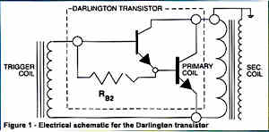
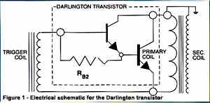
points ever did. Here's how: The magnetron coil actually contains 3 separate coils of
windings. In addition to the primary and secondary windings, there is a 3rd winding,
called the "trigger" coil." When the leading edge of the magnets in the flywheel
approach the coil, the magnetic field surrounding those magnets generates a small
voltage (about 1 volt) that powers a solid-state switching device called a Darlington
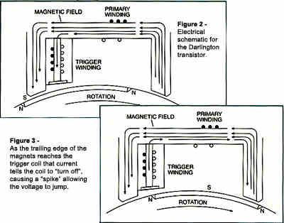
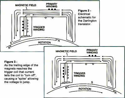
Transistor, turning the transistor "on." That "on" mode completes the circuit on the
primary winding and a current of about 3 amps flows to ground on the crankcase
(Figure 2). As the flywheel continues to rotate that current builds the magnetic
field in the secondary winding.


When the trailing edge of the magnets in the spark plug gap. the flywheel reaches the
trigger coil, a second small current is induced in the trigger coil and that current
tells the transistor to "turn off", effectively breaking the circuit of the primary
winding to ground (Figure 3). As we discussed last month, the sudden break causes the
magnetic field to collapse. Since current (amperage) and voltage are inversely
proportional, suddenly stopping the current flow causes the voltage to "spike" as it
compensates. It's that spike that builds the voltage required in the secondary
winding to jump the sparkplug gap and ignite the mixture. By the way, in the
Magnetron coil, the primary winding has 74 turns of wire and the secondary has 4400.
That's a 59.5:1 ratio and that helps insure that there's enough voltage to get the
job done. All this, the initial current in the trigger coil, the buildup of
potential, the second trigger coil pulse, and the collapsing field with the resulting
voltage spike and spark, in on about 10 degrees of crank rotation. That means that at
6000 RPM the whole thing, start to finish, only takes about 0.00027 seconds. Pretty
amazing.

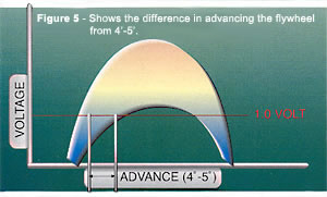
This simple, but very effective, spark control system even advances the ignition
timing, causing the plug to fire earlier (in degrees of crank rotation) as RPMs go
up. You may recall from the part on of this series (NKN January,2000) that "the rate
at which (the) potential develops determines its magnitude." In other words, the
faster you spin the magnet on the flywheel past the windings in the coil, the greater
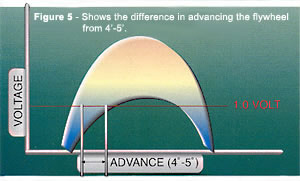
the potential voltage that is developed. Since it only takes about 1.0 volts from the
trigger coil to turn the Darlington transistor on (and off), the faster (in terms of
crank rotation degrees) the potential builds to the required 1.0 volts, the earlier
the induced current in the primary side of the coil will begin to build. And
likewise, the earlier the second trigger coil potential reaches 1.0 volts, the
earlier it will turn the transistor off and trigger the spark process. Take a look at
Figure 3 to see how this advances the timing.
I know this sounds like a lot of engineering gobbledygook. But what it means to you
as a racer is, the faster you turn the engine, the earlier the spark occurs in the
rotation of the crank. "Advancing" the spark is something that engine tuners from
karts to NASCAR have played with for years. Most big-car ignition systems have had
built-in ignition advance for decades. In more recent years, old mechanical systems
to change the timing in the distributor have been replaced with sophisticated
electronic engine control systems. The Briggs "Magnetron" system does exactly that,
cleanly, efficiently, and reliably.

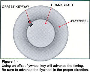
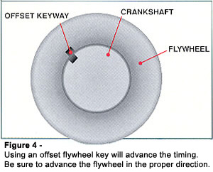
Probably the most commonly used ignition-tuning tool on the Briggs & Stratton 4stroke
is the offset flywheel key. Every kart shop carries them and the savvy Briggs racer
carries a selection to adjust the engine to the track. Basically, these little
machined pieces replace the stock Briggs 1/8" X 1/8" flywheel key. Although they are
sometimes marked in thousandths of an inch offset, more commonly they are identified
by degrees of offset. In other words, how many degrees of crank rotation do they move
the flywheel from the stock position. Most engine builders building methanol-burning
Stock-class engines usually send their engines out the door with 5 degrees or so of
offset. That amount of advance provides a reasonably safe performance increase
without too many headaches for the less experienced or adventurous tuner. Part of
that improved performance comes from starting the combustion process itself earlier
and thus optimizing the point at which the combustion chamber pressure reaches its
peak. Another part comes from the fact that the methanol/air mixture burns somewhat
more slowly than a gasoline/air mixture for which the engine was designed. So you
gas-classers out there take note; 2 or 3 degrees is a better place for you to start.

The 1980's ushered in the magic black box, Magnetron™ ignition coil, Briggs &
Stratton's first truly electronic ignition system. Breaker point ignition systems for
most small air-cooled engine manufacturers have totally disappeared over the last 20
years. In a point style system, the flywheel magnets rotate past the legs of the
ignition armature. The armature itself is made up of two separate windings of copper
wire - the primary and secondary - one wound on top of the other. Basic physics tells
us that when a magnetic field (flywheel magnet) cuts through (moves past) a conductor
(copper wire), a flow of electrons (electricity) is created. However, electron flow
only occurs when we have a complete circuit.  This means that the points must be
closed. We're also told that the faster the movement between the field and the
conductor, the greater the output.

Remember science class in grade school? At one point in your school career, an
enterprising teacher wrapped a length of copper wire around a nail and hooked the
wire ends to a dry cell battery. A handful of paper clips was instantly attracted to
the nail and fell away when the battery was disconnected. Electron flow through a
conductor then, causes a magnetic field. When the points close, electron flow causes
a magnetic field to be created around the primary. This field also envelopes the
secondary. The points now open, break the circuit and collapse the field through the
primary. The field caving in on itself is movement just like the rotating magnetic
field of the flywheel. This movement is at speeds much greater than the flywheel
could spin - near the speed of light. The rapidly collapsing field tears through the
secondary winding which has sixty turns of wire for every one turn of the primary -
effectively generating 60 times the voltage created in the primary. The sum total of
this is that the secondary winding can create up to 25,000 volts in some systems,
which is used to jump the air gap of the spark plug and ignite the fuel/air mixture
in the combustion chamber.

Now for the black box. Magnetron™ solid state ignition systems, in essence, replace
the mechanical breaker points with a transistor. That is, we replace a mechanical
switch with an electronic one. No moving parts, no arcing, no adjustments and solid
state reliability.

Remember speed is a factor. The engine must be pulled over at a minimum speed of 250
RPM before the coil will even think about firing. Thick oil on a winter day or a
heavy parasitic load may cause problems. Customers come into play here as well.
Shorter or elderly individuals may not have the leverage or strength required to
reach the RPM required to activate the Magnetron's electronics.

The tester electrode gap is .166" wide. Those wise in the way of electrons have
calculated that it takes around 13,000 volts to jump this gap. We need 10,000 to jump
the gap on a cold spark plug.

When under compression, the plug requires twice the voltage to fire.

Briggs & Stratton air gaps cannot be made too wide to prevent spark providing the
coil is healthy and the engine is spun over fast enough. A wide air gap, say .030"
will ever so slightly retard the ignition timing as the magnetic field takes longer
to build within the coil windings.

B&S


--
The Rotary Engine News Letter. Powered by Linux.
ACRE NL web site. http://www.rotaryeng.net
You Tube key word PaulLamar2
Copyright 1998-2012 All world wide rights reserved.