Hi  Paul.

 1)  Aside  from   perceived  poor  fuel  economy  of  rotary
 engines, what  are  its  disadvantages ?

 2)  You  advised  carbs  and  magnetos.Why  are  they  not  discussed
 here?
 Are  they  not  suitable  for  rotaries ?   If  suitable,   Let's
 have  more  discussions.

 3)  Can  there  be  carb  icing  in  tropical  countries  below  3,
 000 feet ?

 Best regards.
 Ben

 Fuel economy is only 5% higher than an aircraft piston engine.
 This is more than made  up for by the 25% lower cost of auto gas.

 Magnetos are suitable. They will work fine.  They are just too costly.
 $2000 each new
 and $400 to $800 re manufactured plus cores. People don't want to
 pay as much for two  aircraft magnetos as they pay for the rest of
 the engine. In some cases much more than  they payed for the engine.
 RX8 ignition coils are $25 each for a total of $100. One  coil per plug.

 However if I were certifying a rotary I would use aircraft magnetos
 and an aircraft carb. The FAA is much more comfortable with that they
 they are with
 EFI and electronic ignition. In that case the rotary engine would pass
 certification
 in a heart beat.

 The best carb (cost verses power) to use is a two barrel 500 CFM Holley
 with a
 leaning kit.

 The FAA will not sign off on your carb engine unless it has carb heat.

 Paul Lamar

 Thanks  Paul.

 I'm  glad  there  is  someone  like  you  who
 has  the  knowledge  and  patience  to  answer
 our  questions.

 Can  there  be  carb  icing  in  tropical  countries  at  an
 altitude  up  to 4,000 feet ?

 Best regards.
 Ben

 At the higher altitudes for sure. The evaporation of the fuel in
 the carb venturi causes a cooling effect.

 Paul Lamar

 Paul,
 My Continental IO 520D has fuel injection- but it is a very basic system
 indeed. One inj per cyl, a regulator, and a mechanical "TPS". It
 looks like it all related back to the manual leaning valve and quite
 possibly the manifold pressure. This system seems remarkably like
 the old FI on the corvettes in the early 60s. Regulators and manual
 flow metering.

 Why would this be a difficult system for the rotary? Before I sell my
 Connie, I might inventory the system and see about maybe a prototype.

 Kevin Alderman

 http://www.vette-vues.com/parts_for_sale.html

 Early Power Sport used mech fuel injection.
 It is still sold for aircraft.
 http://www.airflowperformance.com/html/site_html.html

 Paul Lamar


 These early Rochester FI systems were not received well due to a couple of
 things. The dual quad made more power the next year and the injection was very
 sensitive to atmospheric conditions. It required almost daily tuning unless
 someone really knowledgeable worked on it.
 Att 1.  The "throttle" in the center is not the throttle. It is the choke
 plate.  The throttle can be more easily seen in Att 4.
 This works similar to the Bosch/Volkswagon FI and the Mazda MCES systems,
 that use a special volute and flapper to measure air flow. The Rochester used
 the cone in the intake to create a pressure drop like a venturi. This was fed
 over to the diaphragm to lift the metering "rod" to add fuel. At idle there
 would be no "vacuum" on the sensing line. As the throttle is depressed, the
 air flow causes a vacuum at the venturi and lifts the diaphragm. Different air
 densities and humidity affected the fuel required which was not well
 compensated for. The Mazda MCES works fairly well as the sensor is a form of
 mass flow and is compensated with the computer. The Bosch also works as a
 basic mass meter, but did not have a computer (Rabbit system. different from
 K-jetronic).
 Any AC system will have compensation for atmospheric condition as a
 requirement for altitude changes.

 Dale Davies


 Hi   Paul,
 No FI system I have ever flown with has allowance for
 temperature or density, only have experience with Cont and Lyc. My understanding is
 they are both a engine speed/throttle/mixture position, ie if you have the
 mixture,prop,throttle to the wall you will always get the same fuel flow, regardless
 of temperature and,or altitude. But I love 'em, no carby icing!! BUT if you have
 clogged injectors your fuel flow gauge will tell you you have say 36 gallons pre hour
 at take-off, you will have something less than that, because it is not a fuel flow
 meter but purely a pressure gauge! calibrated to indicate fuel flow in gallons per
 hour. Where it become bad is if you have only one injector, you may not notice the
 fuel flow is lower than it should be for that engine, unless you have  EGT probes in
 each exhaust outlet.
 John Burey


 Hi  Paul,   I was half asleep last missive I think, I had said "if
 you have only one injector", I really wanted to say was that if you had
 (one injector partly clogged), you would have a lower fuel flow to that
 cylinder, which you can pick up with a EGT in each exhaust outlet. Fuel
 injection is much better than carbys every time, as for the spark, I
 cannot see why one could not use a electronic ignition as a previous
 writer described (B&S), one for each cylinder with wasted spark, ie two
 plug wires on each coil, then if one coil failed you would be only drop
 out one plug on opposing cylinders, plus you would have a very hot spark
 with about .040" gap not the pillidy .015" to .020" with a magneto, just
 the correct size gap to catch a bit of carbon, I am surprised that the
 FAA still allow magneto's to be used, I have had more failures with
 magnetos in engines than any other single thing. I know all the reasons
 they are used (no external power) ect., ect..
 John Burey

 Be careful with wasted spark. Only the bottom plugs will tolerate that.

 Paul Lamar


 Hi   Paul, what is the reason for not tolerating wasted spark on the
 top plugs? as you know I nothing, nothing, (in a high pitched
 voice),about Rotarys.
 John Burey

 Waste spark fires two plugs at the same time.

 The problem is rotor 2 is always 180 degrees out of phase with rotor 1 so when rotor
 1 is on the firing stroke rotor 2 is on the compressing stroke with a combustible
 fuel air mixture that might pre ignite causing a negative torque on the e-shaft. You
 can see that with this picture of a transparent model engine.

 In a 2 cylinder or more piston engine, the firing stroke is 180 our of phase with
 an exhaust stroke so the waste spark has no effect on the spent exhaust mixture.

 Paul Lamar back from China.

 What if you hooked the waste spark return to the 2nd plug on the same rotor?  Is
 there enough power to fire both?


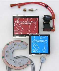
 We are running Klaus' Lightspeed on the little Continental and it works like a charm.

 Chris Cosman

 That should work. Is Klaus using waste spark coils? I think that is a CD system.

 Paul Lamar

 Maybe I don't understand it fully.  We phase the system by positioning the crank at
 TDC (using the prop as a handle), then with the system on (and plugs removed) rock
 the prop back and forth past TDC.  This also moves the tiny magnet back and forth
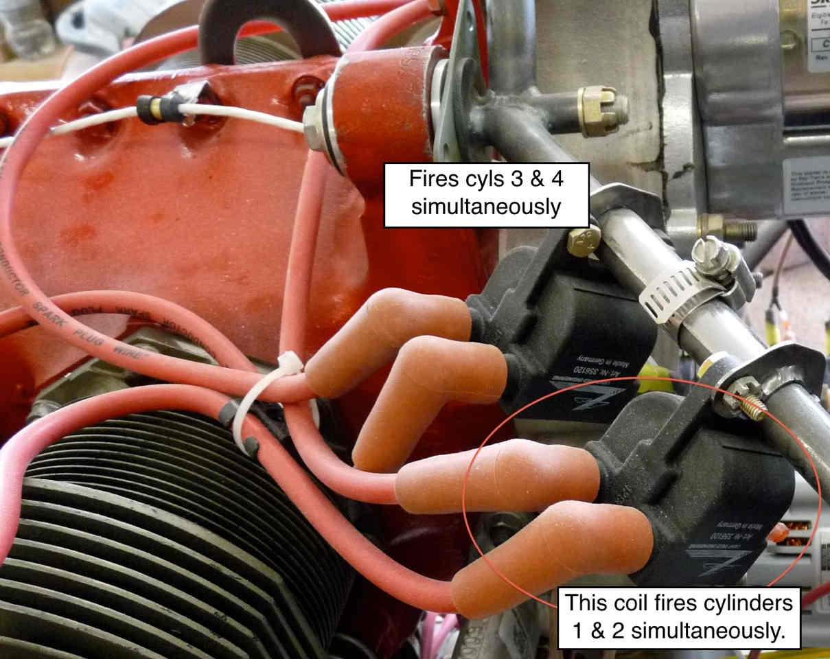
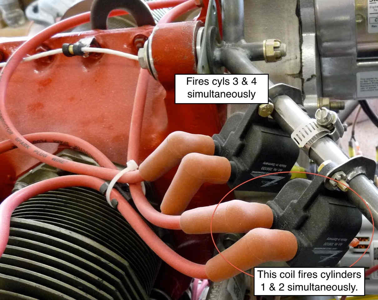
 past the hall effect sensor.  The coil that sparks between the two posts is the one
 that gets hooked to cylinders 1 & 2.  Turning the motor 180 deg. and rocking the prop
 back and forth sparks the other coil which gets hooked to cyls 3 & 4.

 I assumed this was a waste spark system since cyl 1&2 fire at the same time, and 3 &
 4 fire at the same time.


 Chris Cosman

 If it is two coils it is waste spark. How many tiny magnets are there on the disk
 that rotates with the crankshaft?

 Paul Lamar

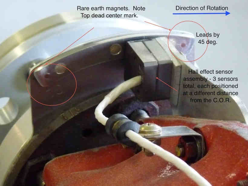
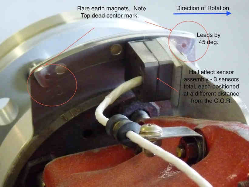
 4.
 One each at TDC, 45 degrees before TDC, BDC, and 45 degrees before BDC.  I see if I
 can get some pix if that would help.

 Chris Cosman

 Does it have a switch for hand propping starting? I suspect the TDC magnet is for
 hand starting. The 45 degrees BDC is to allow high altitude advance and perhaps dwell
 time if not capacitor discharge. Klaus is a bit secretive about how it works.
 The late Paul Lipps designed it and I suspect it is multi spark CDI. I also think
 it fires every rev as there is no cam sensor as far as I know. Is there a device that
 replaces the magneto?

 Currently I suspect Klaus is using mega-squirt on his new Long EZ.

 Paul Lamar

 No switch for hand propping, I think the system retards the spark significantly
 during starting.  When it first fires it runs mildy rough for a few seconds, then
 smoothes out, I assume that is the spark advance kicking in based on motor rpm.

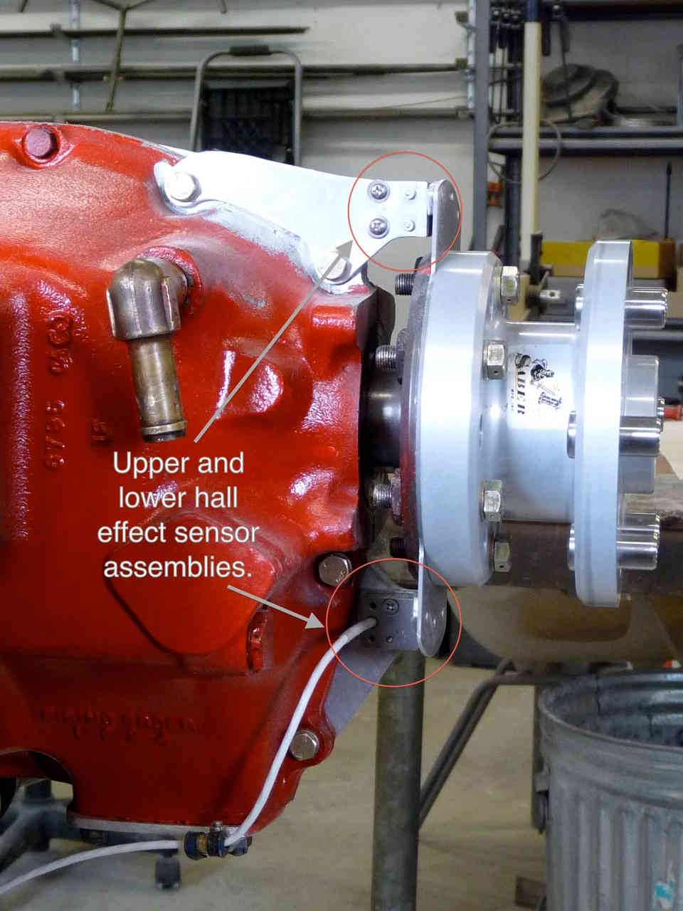
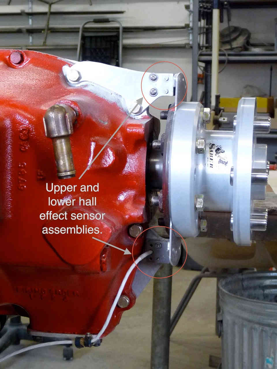
 There is not a device that replaces the magneto. (except the aluminum covers for the
 holes).  The sensor for one system is mounted on the bottom of the motor, and the
 other on the top.  There is a patch cable that allows the two systems to communicate.

 Chris Cosman

 How many hall effect sensors are there on the PC board that goes close to the disk
 holding the magnets. In other words how many wires are coming off that PC board?

 Paul Lamar


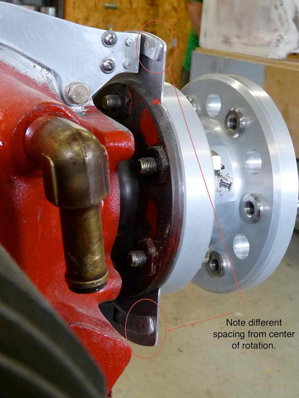
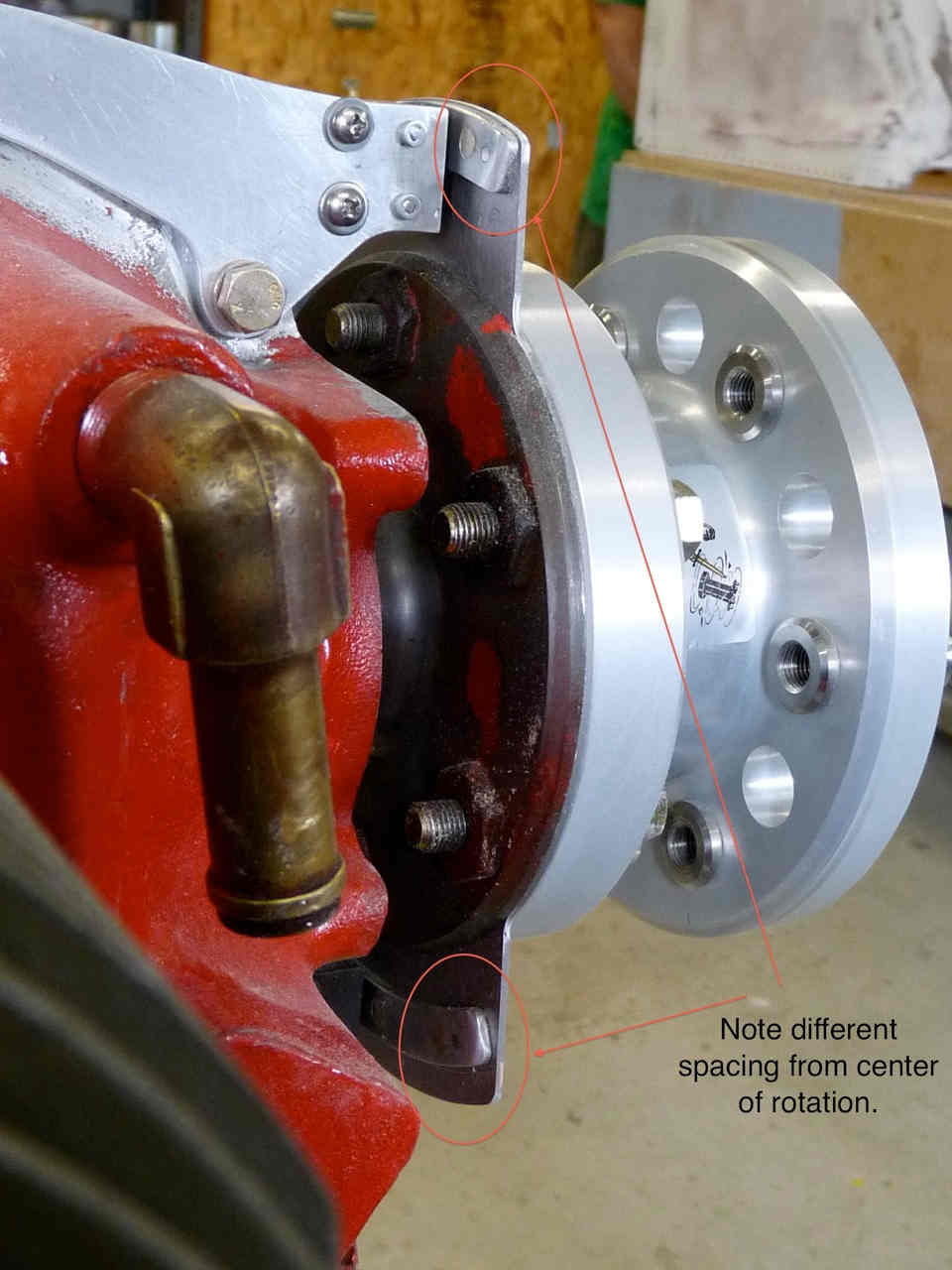
The TDC magnets are located further from the center of rotation (COR) than the BDC
magnets.

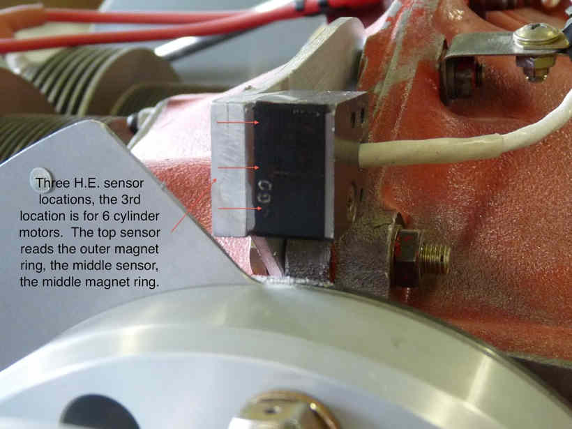
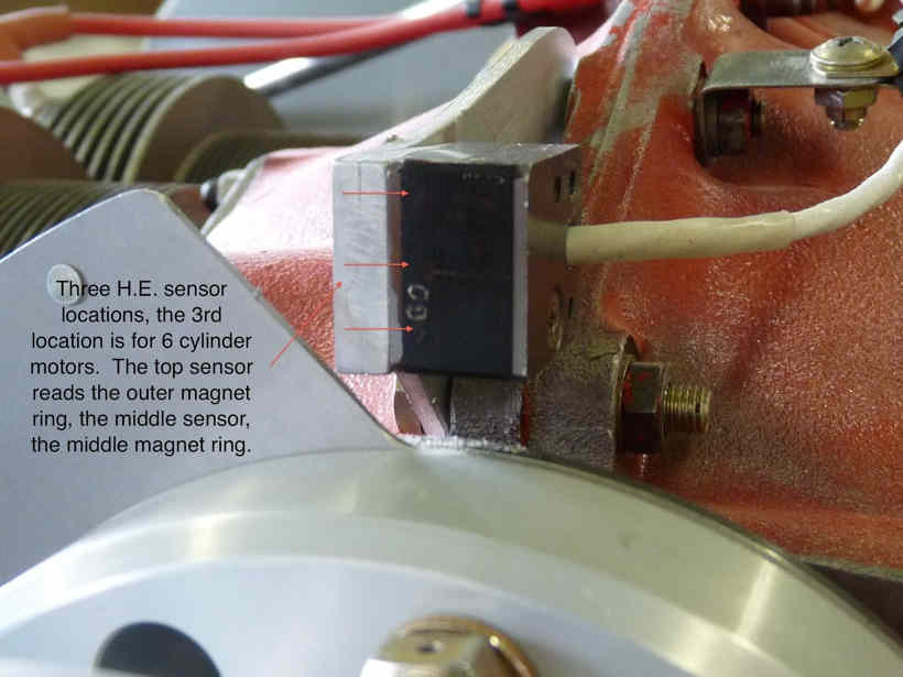
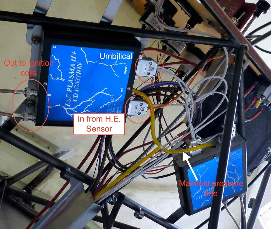
Each Hall effect sensor assembly (2) has 3 H.E. sensors inside; an inner, middle, and
outer, which correspond to the inner, middle, and outer circles  (rings) transcribed
by the magnets.  Since we have a 4 cylinder motor, one of those rings is not used, (
I think it is the inner ring), and the TDC/BDC magnets are located 180 degrees from
each other (instead of 120 for a 6 cylinder).

TDC & BDC both have a leading magnet positioned 45 deg before, when rotating of course.

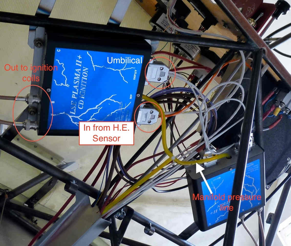
Each sensor assembly reads both sets of magnets.  That info goes back to Klaus'
little box, one for each sensor assy., and those are also hooked together with an
umbilical.

The system fires cylinders 1 & 2 simultaneously, then 3 & 4.  The bottom plugs are
handled by the other box.

Chris Cosman

Good work Chris.
I think this is multi strike capacitor discharge.
Each hall effect sensor fires the plug again.


Paul Lamar
--
The Rotary Engine News Letter. Powered by Linux.
ACRE NL web site. http://www.rotaryeng.net
You Tube key word PaulLamar2
Copyright 1998-2012 All world wide rights reserved.