I have decided to use a turbo p-port 13b on my Wheeler. I have the core
  engine completed and sitting on the engine mount at the moment. Before I
  make the engine mounts, etc. and start laying out the rest of the engine
  compartment I need to confirm a couple of things-

  My plan is to have around 250HP or so (maybe a little more) and end up
 with
  a modest boost at take-off power. The boost will be controlled to maintain
  this power level if desired up at altitude.

  1. The first question is about the intake runners. Is it necessary to
  maintain the 18 inch length of the runners even if I run a turbo? Or, can
 I
  run the turbo discharge into a plenum with just enough tubing to make it
 in
  to the plenum after the throttle plates?

  2. Is sufficient heat available from the cooling water (read heater core)
  to provide cabin heat at high altitudes in cold weather. Here in FL heat
  wasn't much of an issue other than having too much of it, but in the
  Carolinas in the winter I have seen OAT below 0 at 12,500'. That's cold.
  I
  remember that the rotary uses the oil as a means to remove waste heat, so
  would it be a better idea to use oil as a means to heat the heater core
 for
  cabin heat?

  3. There has been a lot of discussion about turbos and getting them to
 live
  longer than an hour or 2 with the rotary. I have found 2 types of turbos
  that are described as "continuous running"- one has ceramic bearings and
  the other has a "floating journal".  Advice here would be helpful- the
  turbo I select will determine the exhaust header selection.  A model
 number
  or something would be a great start.

  Kevin Alderman

  On the intake length the 18 inches are still an advantage with a turbo as
  during
  the low boost phase there is still a breathing advantage. That translates
  to slightly
  lower fuel burn per HP generated.


  If you send me a sketch of the fire wall I'll do a 3D layout of the motor
  mount
  and turbo installation.

  The KIS  shown has a higher thrust line than most aircraft so the position
  of
  the thrust line relative to the top of the firewall is important for 18
  inch runner
  clearance.

  Paul Lamar


 I am using the Viking mount that I have- the Viking is 4 inches narrower
 than the Wheeler but that was a minor modification.  The problem at the
 moment is the thrust line and the cowl that came with the plane. When the
 engine is centered up I only have 1 inch or so between it and the cowl on
 top. I measured my Connie and the only way it would have worked is because
 the high point is at the extreme rear at the mags. The mags would have been
 about 1/2 inch from the cowl. I can get more clearance by lowering the
 thrust line, not my first choice.

 The later Wheelers have a conventional tail not the cruciform tail that I
 have- and the thrust line is about 2 inches lower. I assume that the tail
 had something to do with placement of the thrust line. The only recurring
 complaint about the CT Wheeler is that it has low tail authority on
 landing. Moving the propwash and thrust line down might make this worse.

 The good news is that my cowling is 46 inches long- which gives me about a
 half acre under the cowl for the engine. The 13B looks quite small naked
 under there at the moment. I have the plane blocked up at the spar, and
 with the engine sitting in place I still need 100 lbs just to get a neutral
 CG. With that info, I need to get as much of the engine done as possible
 (hanging parts on it) so that I can get my WB right.
 Which means turbo, etc. is up on the list.

 I have reservations about using the cooling air ducted into the cockpit.
 The cowl flaps that you showed are under the plane at the exhaust- and any
 exhaust leakage particularly under the cowl would be directed into the
 cockpit. My ventilation is through NACA vents on either side of the plane
 well away from any exhaust. The air from these vents will be ducted through
 air vents to the passengers, or can be diverted through an RX8 heater core
 mounted behind the panel.

 Kevin Alderman

 Yes I can see that you have less clearance under the the cowl than a KIS
 cruiser.
 That rules out the 18 inch up and over intake runners. I assume you are
 using the
 Viking nose gear as well. Moving the thrust line down without moving the
 entire motor
 down would affect the prop clearance as well of course.

 Your scheme of using a beam to pick up the front connie mounts will work
 well with a
 custom oil pan. That will put the engine/GB/prop CG right over the front
 connie
 mounts. The rear connie mounts can be ignored.

 We used to use that and called it a Schertz beam. It was patterned after
 the QuestAir
 Venture mount. Here is some shots of the QA set up.

 I assumed you were going to use a simple 180 degree side exhaust out of
 the turbo but
 a RX8 heater core will also work well.

 I can still do a 3D of your set up if you give me a few dims such as the
 distance of
 the thrust line down from the top of the firewall and the dims between
 motor mount
 points.

 Paul Lamar


I will be out of town (read away from the airplane project) for a week, I
can document the dims  on the mount when I get back. I have decided not to
use the Viking nose gear- after a LOT of work I just cant get the
retractable gear to work in the wings, the Wheeler wing is too thin. So, I
will use the Wheeler factory fixed gear setup with the castering nose gear.
The Wheeler has no provisions for steerable nose gear, as it was designed
to be steered with differential braking. So, to avoid lots of extra work I
went back to the original. I was willing to adapt the plane for retractable
gear, but not just for the nose.

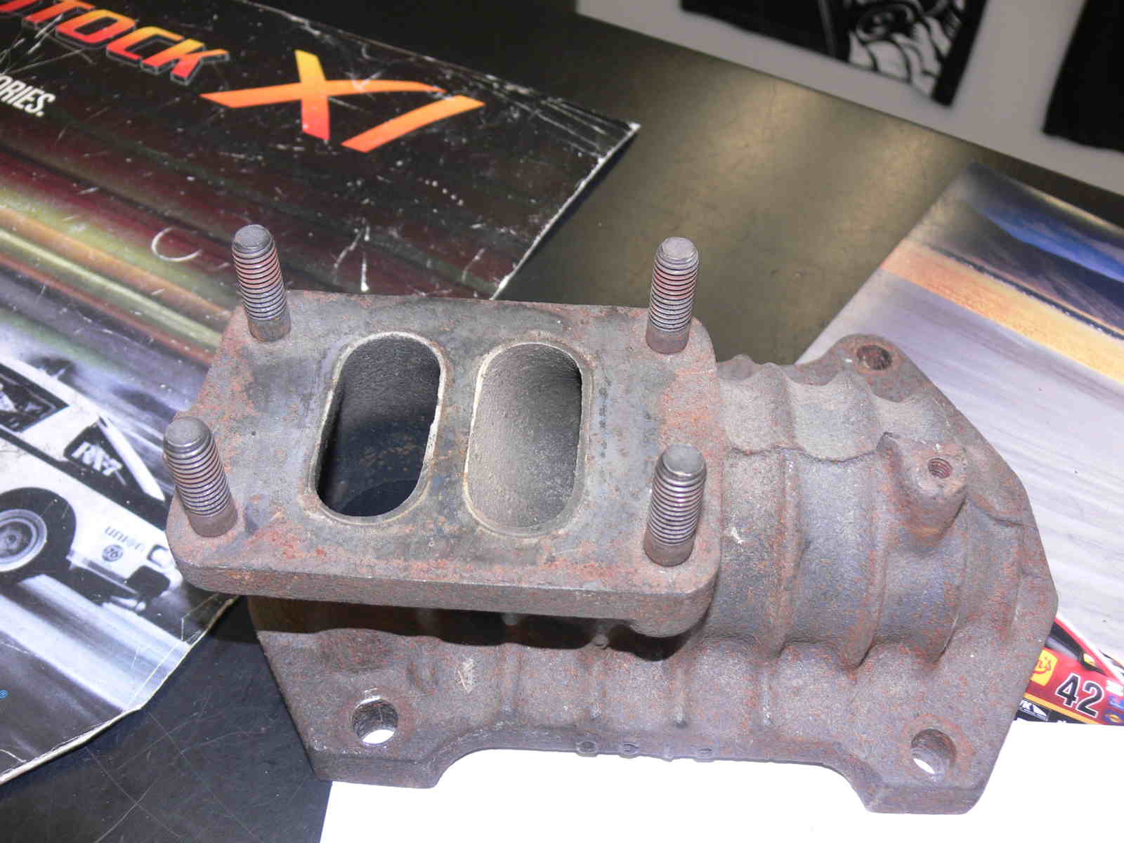
Do you have a  known thickness for a header for the turbo that will work
for this application? I have found several made from SS, but I want to make
sure that they will not burn through in the air.

Back to the intake runners, I do have plenty of room to route the intake
runners up and rearward (toward the firewall) and keep them in the range of
18".

Kevin Alderman

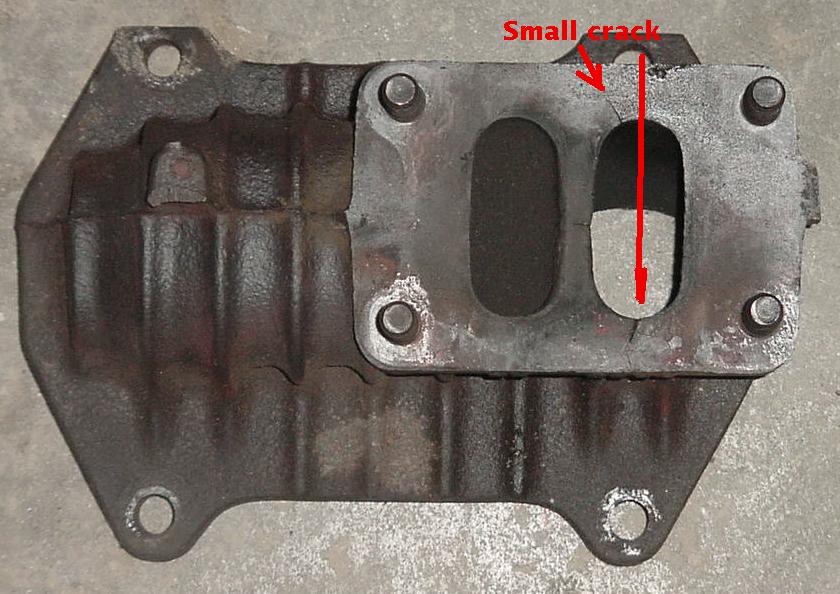
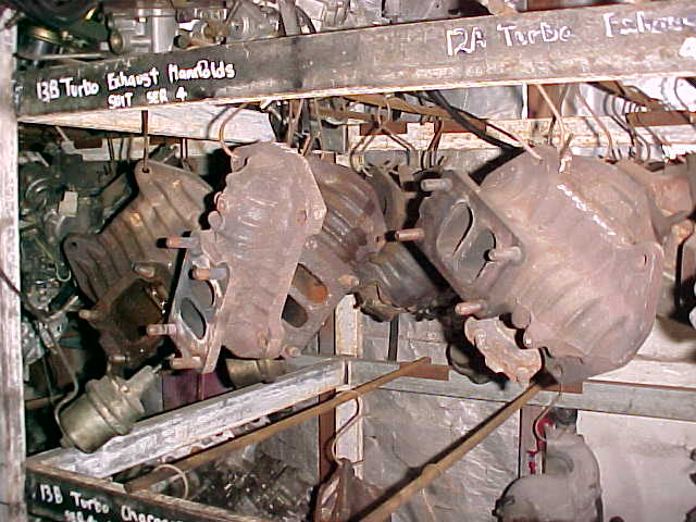
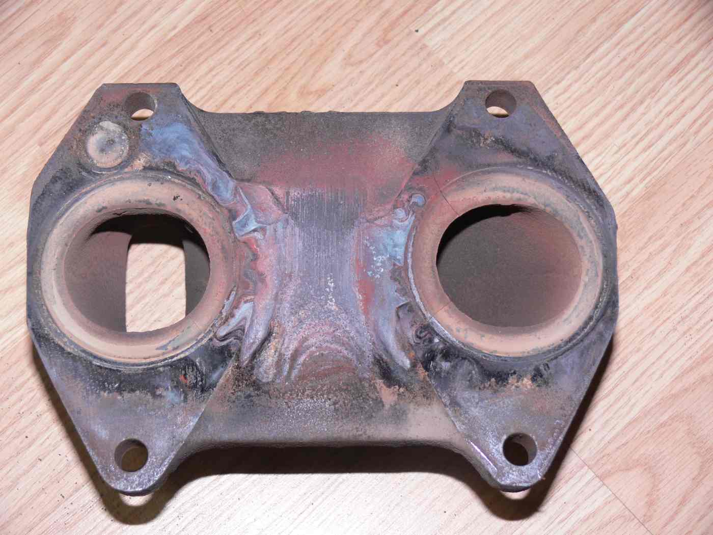
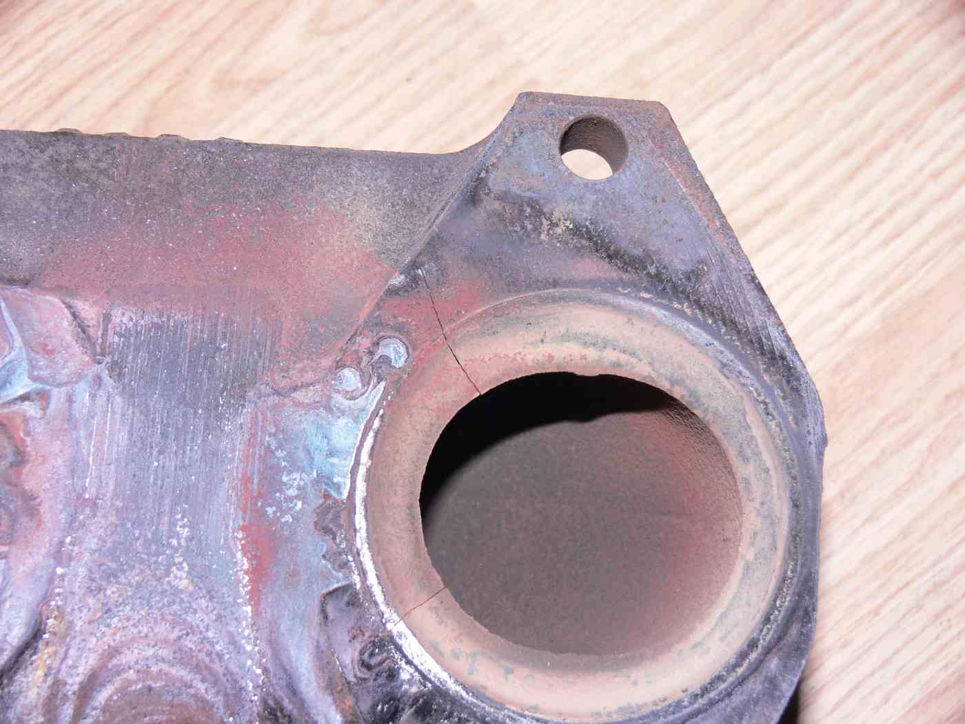
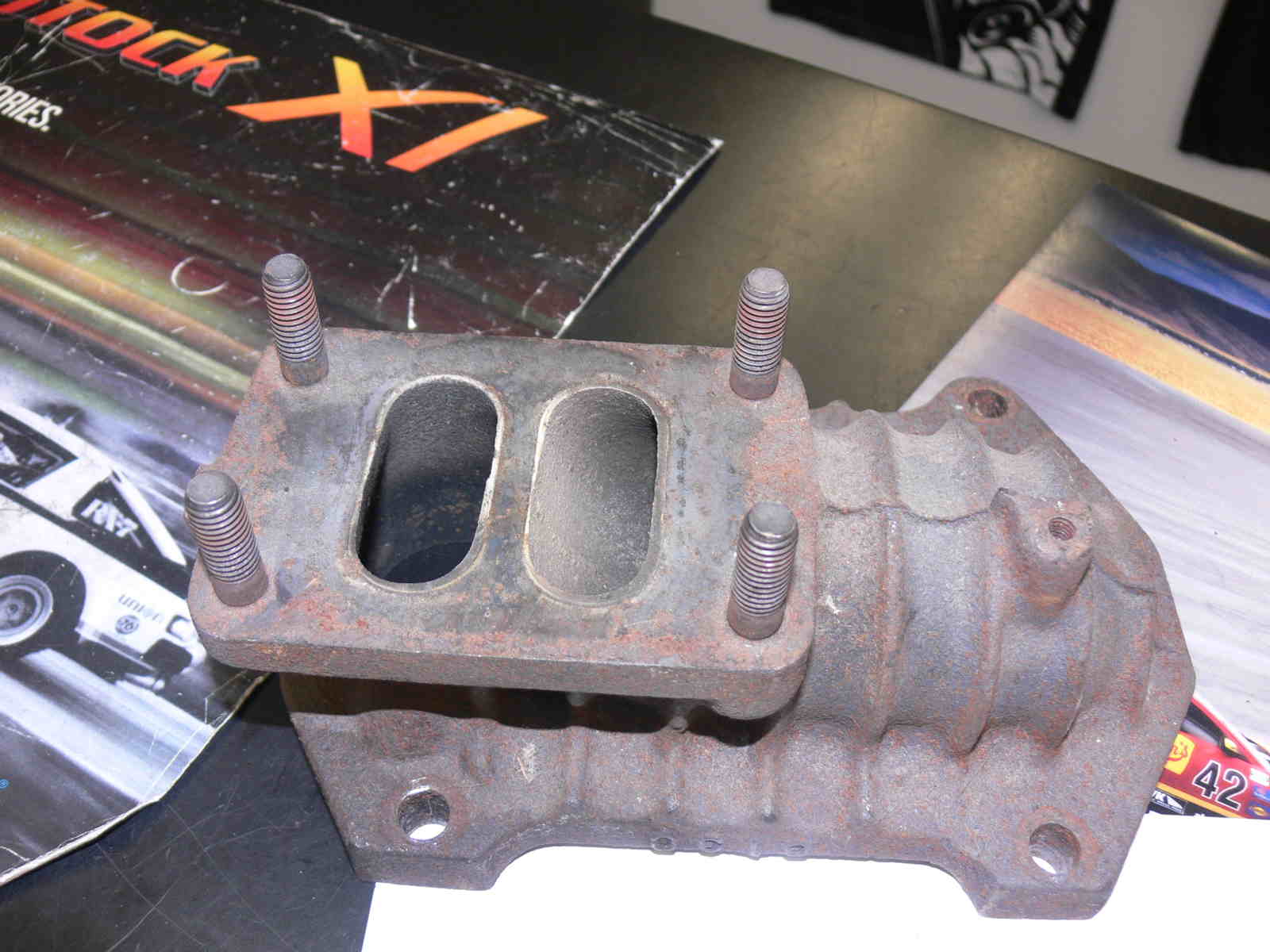
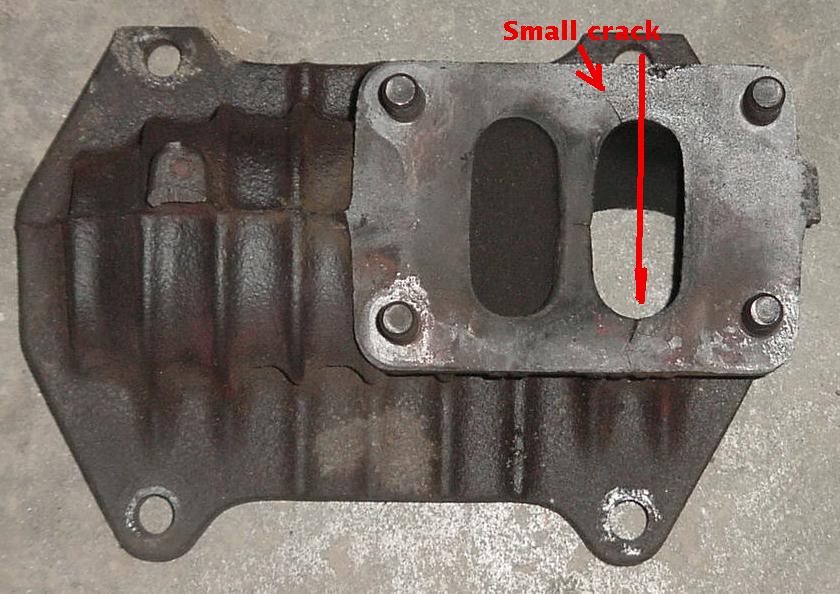
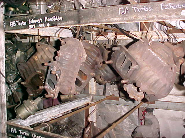
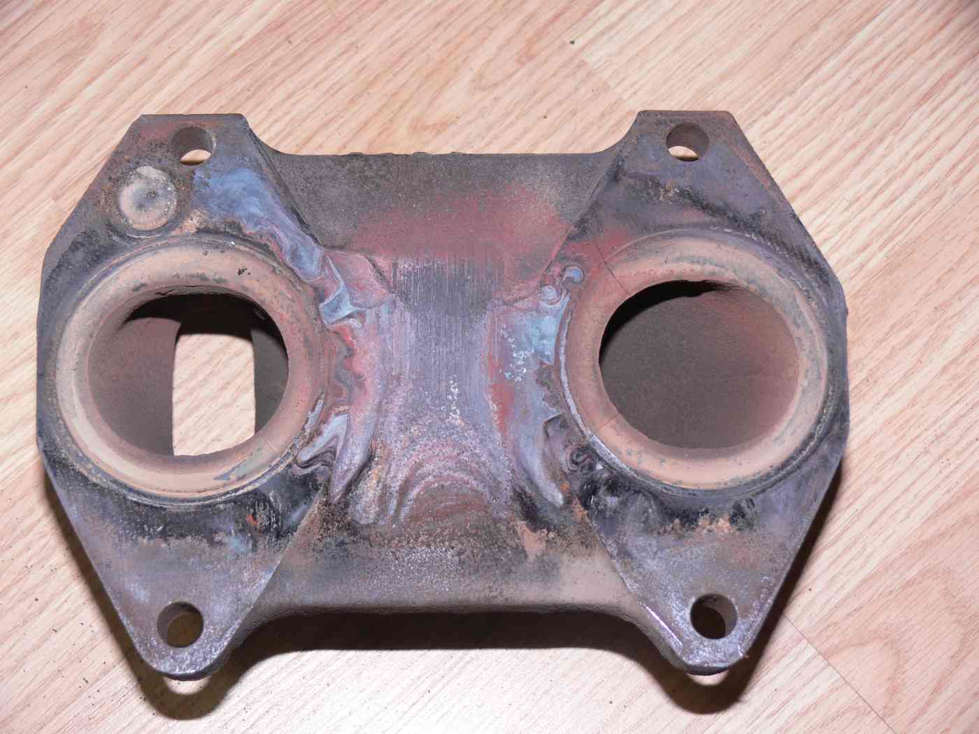
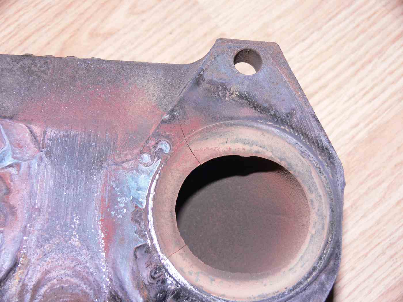
The stock 2nd gen will work but most used ones are already cracked.
The sharp machined edges need to be radius-ed with a die grander.

V out the cracks and weld them up. It will last 5 years.

Paul Lamar


 --
 The Rotary Engine News Letter. Powered by Linux.
 ACRE NL web site. http://www.rotaryeng.net
 You Tube key word PaulLamar2
 Copyright 1998-2012 All world wide rights reserved.


--
The Rotary Engine News Letter. Powered by Linux.
ACRE NL web site. http://www.rotaryeng.net
You Tube key word PaulLamar2
Copyright 1998-2012 All world wide rights reserved.